Modular controller for a hot melt adhesive dispensing system

Inactive Publication Date: 2005-12-20
NORDSON CORP
View PDF4 Cites 4 Cited by
  • Summary
  • Abstract
  • Description
  • Claims
  • Application Information

AI Technical Summary

Benefits of technology

[0008]In another exemplary embodiment, the power modules are configured to be directly connected to cord sets associated with heated hoses of the adhesive dispensing system. This configuration eliminates the need for a connector plate and wiring harnesses between the cord sets and power modules, as is typical of conventional controllers, thereby further facilitating ready removal and replacement of power modules in the field.
[0009]In yet another exemplary embodiment, the power modules are mounted to side panels that have heat dissipating fins provided on an outer surface of the panels, whereby thermal management of the controller may be achieved without the need for additional heat sinks to be attached to the controller.

Problems solved by technology

However, the configuration of conventional controllers makes upgrading or other modification of the controller costly and very labor intensive.
Furthermore, with some systems upgrading is not even possible.
Such infiltration may occur, for example, by accidental spillage of liquid near the adhesive dispensing system, or by exposure to liquids during cleaning of the adhesive dispensing system or the immediate area surrounding the system.

Method used


Image

  • Modular controller for a hot melt adhesive dispensing system
  • Modular controller for a hot melt adhesive dispensing system
  • Modular controller for a hot melt adhesive dispensing system

Examples


Embodiment Construction

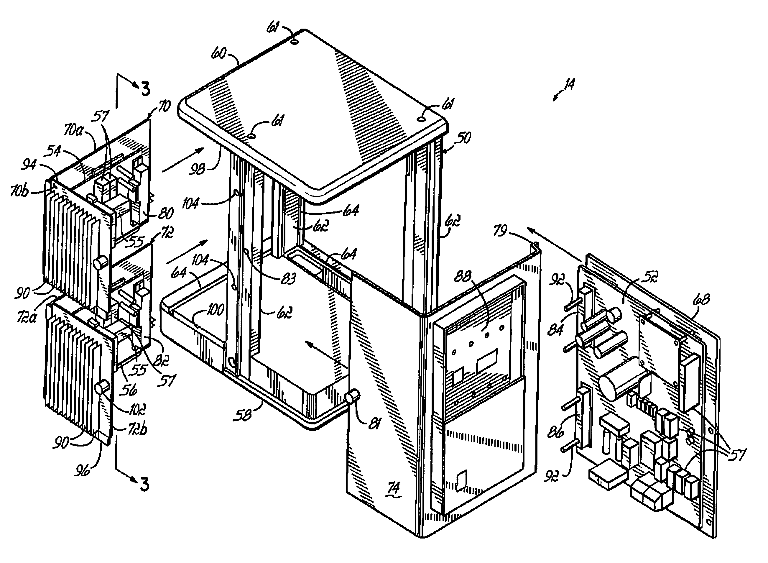
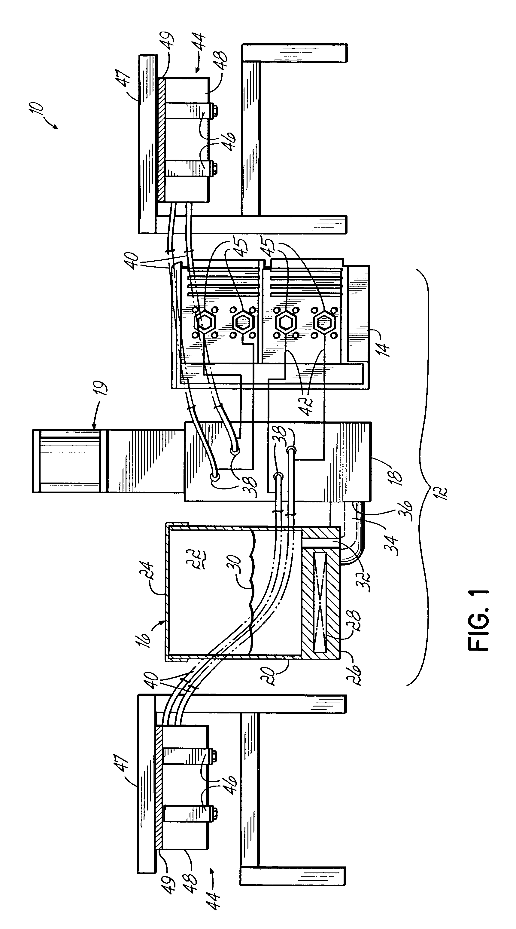
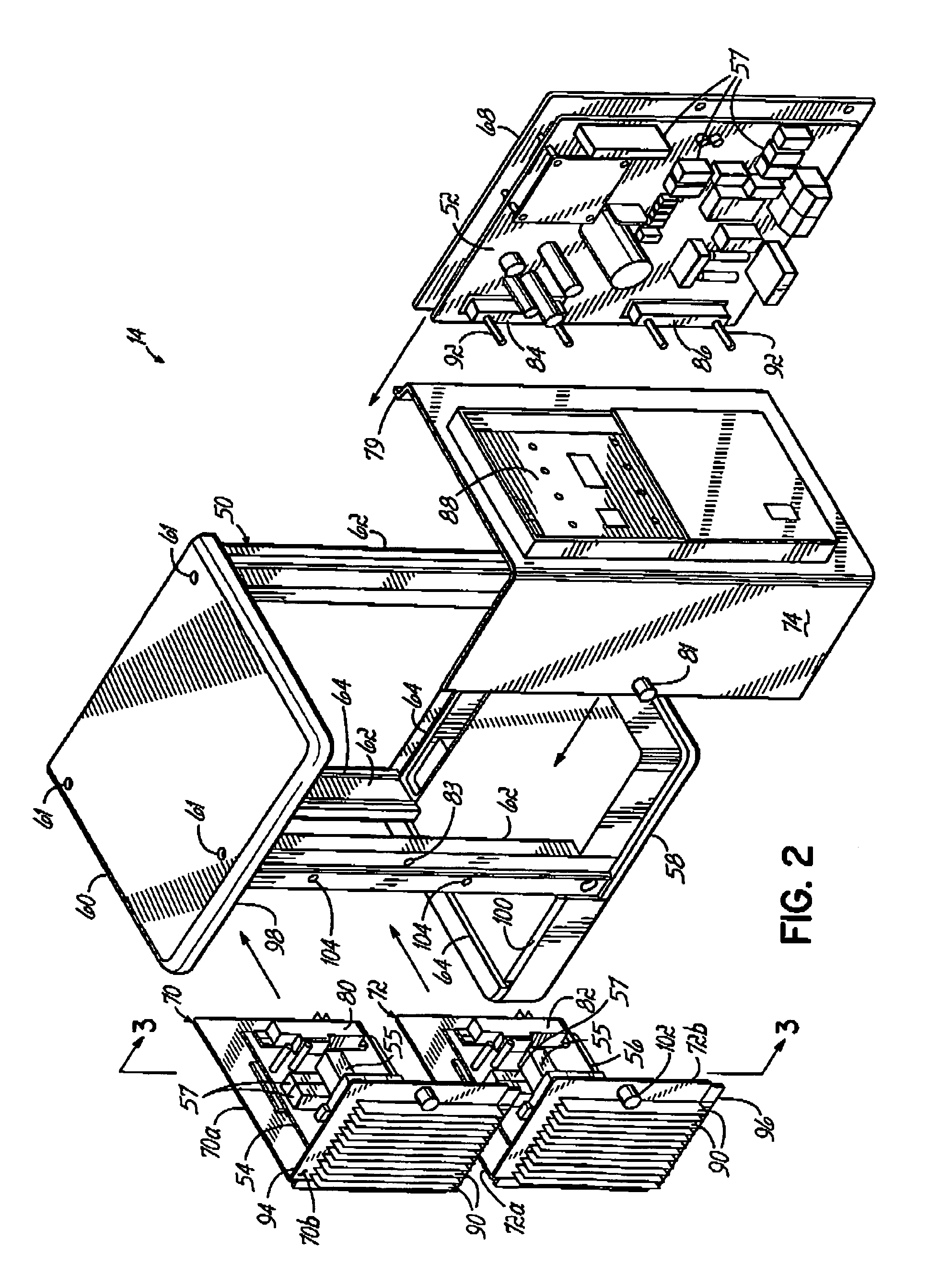
[0020]Referring to FIG. 1, a hot melt adhesive system 10 is shown, including a dispensing unit 12 which incorporates an exemplary controller 14 according to the present invention. The dispensing unit 12 further includes a tank 16 for receiving and melting solid or semi-solid adhesive material, a manifold 18 connected to the tank 16, and a pump 19. The tank 16 comprises side walls 20 defining a tank interior 22, a removable cover 24, and a base 26 which includes a tank heater 28 for melting and heating the adhesive material 30 in the tank 16. A tank outlet 32 proximate the base 26 is coupled to a passage 34 which connects to an inlet 36 of the manifold 18. The pump 19 is coupled to the manifold 18 and pumps liquid adhesive 30 from the tank 16 and into the manifold 18 where it is split into separate flows. The manifold 18 has a plurality of outlet ports 38 which may be fitted with heated hoses 40 attached to one or more adhesive guns 44 to supply the liquid adhesive to the guns 44. Th...


PUM


Abstract

A controller for a hot melt adhesive dispensing system has a main circuit board and power modules which are removably received on a controller enclosure. The power modules are directly couplable with the main board and with cord sets from heated hoses of the dispensing system, eliminating the need for wiring harnesses to be routed between these components. Accordingly, the main board and power modules may be readily removed and replaced in the field to permit efficient servicing and modification of the system to accommodate the needs of various applications.

Description

FIELD OF THE INVENTION[0001]The present invention pertains to dispensing systems for dispensing flowable material, and more particularly to hot melt adhesive dispensing systems.BACKGROUND OF THE INVENTION[0002]Thermoplastic adhesives, otherwise known as “hot melt” adhesives, have been widely used in industry for adhering many types of products. Hot melt adhesive dispensing systems generally include one or more adhesive dispensing guns, heated hoses connected to the guns, and a dispensing unit for melting and supplying liquid adhesive to the guns through the heated hoses. The dispensing units of conventional hot melt adhesive systems can include a tank and heater, a pump, a manifold, and a controller. The manifold has an inlet connected to the tank and has multiple outlet ports for fluid connection to the heated hoses. Adhesive material is supplied to the tank in solid or semi-solid form, where it is melted and heated by the heater. A pump associated with the tank and manifold pumps ...

Claims


Application Information

Patent Timeline
IPC IPC(8): B05D7/24B05C5/00B05C11/00B05C11/10
CPCB05C11/10B05C11/1042B05C11/00
Inventor SUCKOW, DANIEL J.MEANS, SCOTTFORNEY, SEANFISHER, DUANE
Owner NORDSON CORP
Why Eureka
Try Eureka