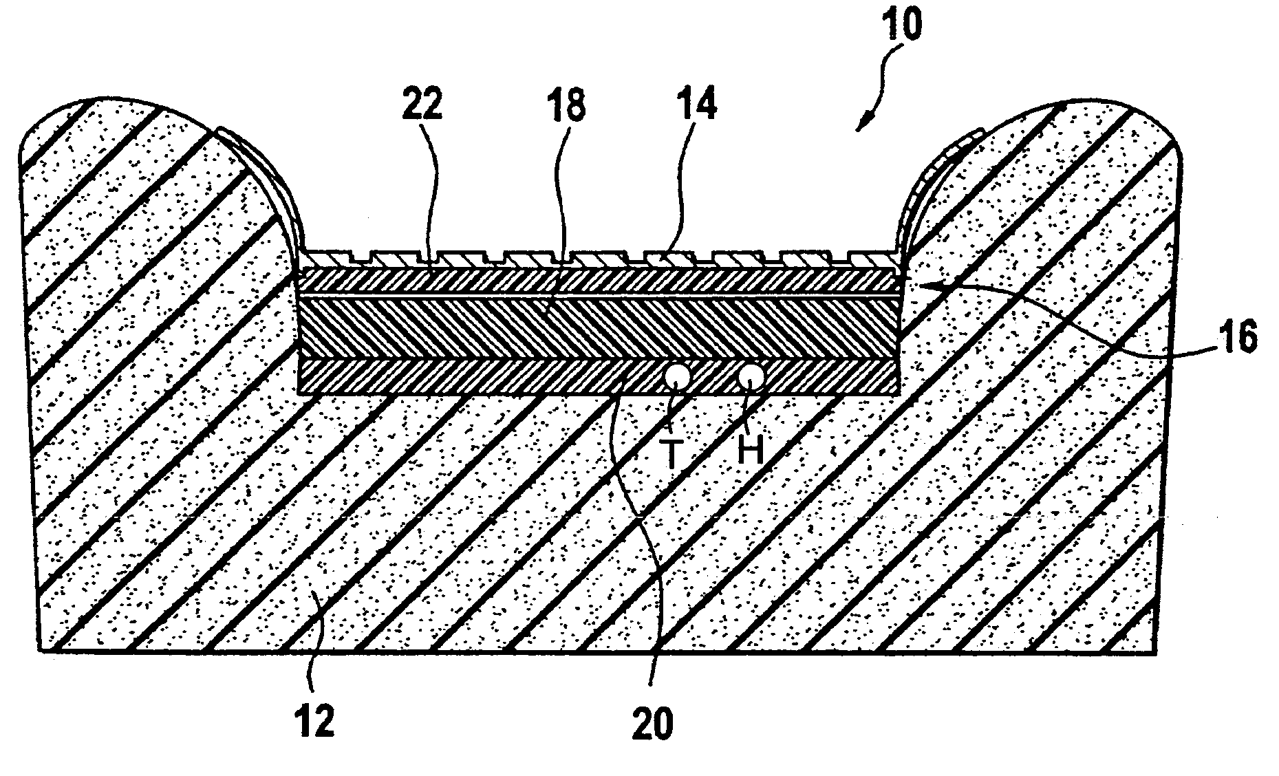
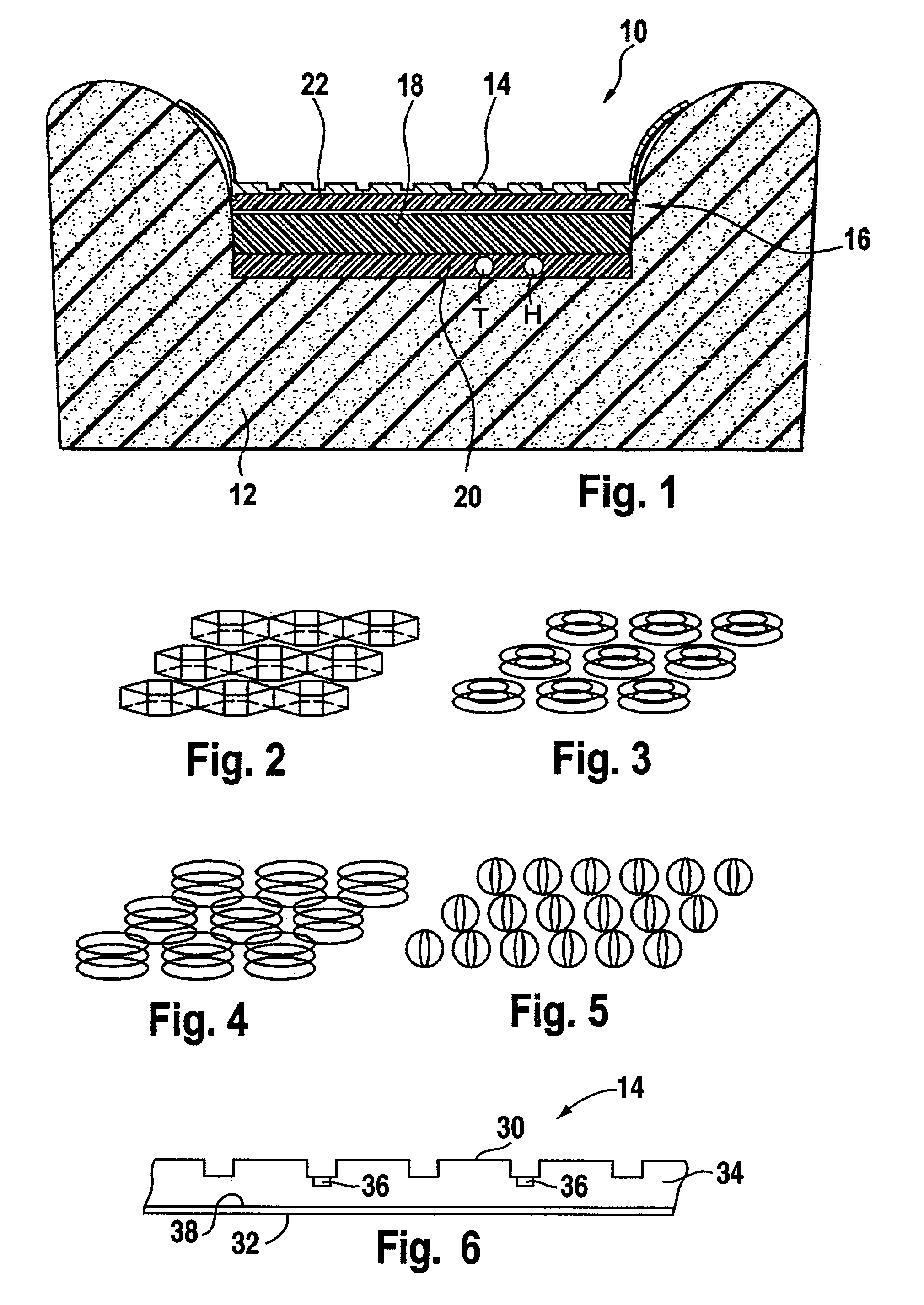
[0008]In accordance with the invention, this objective is achieved by a detection device for automobile seat, comprising a flexible pressure sensor and a decoupling layer fixed on the
lower face of the pressure sensor, said decoupling layer comprising a constant modulus of elasticity. The decoupling layer forms a support for the pressure sensor, which exhibits a constant modulus of elasticity. The pressure sensor is consequently decoupled from the foam of the seat, which foam exhibits a modulus of elasticity that is quite variable with temperature and over the lifetime of the seat. It follows that with the detection device of the present invention, the reaction of the support of the pressure sensor is largely independent of the temperature conditions and of the age of the device. Consequently, the device is characterized by a constant mechanical behaviour within a wide range of temperatures. Moreover, the
mechanical strength of the decoupling layer is stable over the lifetime of the device, allowing reliable detection over the entire lifetime of the seat.
[0009]In a preferred embodiment, the decoupling layer comprises an
open structure with a lower layer and a spacing structure disposed on said lower layer. An
open structure such as this is favourable to circulation of air in the decoupling layer and consequently allows very effective ventilation of the detection device and of the seat. Moreover, the decoupling layer is preferably composed of hydrophobic or at least non-hydrophilic materials, so that the
drying of the seat by circulation of air is facilitated. It follows that the comfort of the seat can be considerably improved as compared with a seat comprising a conventional detection device.
[0010]Said spacing structure can comprise flexible spacer elements distributed over a surface of the lower layer. These spacer elements comprise for example
neoprene blocks and / or rubber rings and / or
metal springs and / or pockets filled with a gas. These elements provide for stability of the mechanical properties of the decoupling layer over a long lifetime. It should be noted that the number of spacer elements determines the
mechanical strength of the decoupling layer, that is to say its modulus of elasticity. It is therefore possible to tailor the strength properties of the seat / sensor
assembly to a large extent, that is to say to influence the comfort of the seat. It will be appreciated that this modulation of the comfort of the seat may also be achieved through a combination of different
layers having different hardnesses.
[0013]The lower layer may also comprise a nonwoven layer, which will advantageously facilitate the mounting of the detection device on the foam of the seat e.g. by bonding or by a self-fastening
system.
[0014]In an advantageous execution of the detection device, a
heating element is integrated into the decoupling layer. In such an execution, the detection device and the seat heating form a prefabricated module with preferably a single connector that can easily be installed on the seat. The integration of the
heating element into the decoupling layer moreover makes it possible to minimize the interference between the
heating element and the pressure sensor. It should be noted that the
open structure of the decoupling layer encourages the
convection of the heat emanating from the heating element, thereby ensuring good dispersal of hot air in the seat and increasing the comfort of a seat equipped with such a device. It will be appreciated that the heating element will advantageously be integrated into the nonwoven lower layer. Such an execution protects the passenger from any sense of burning and protects the seat trim (in particular the leatherwork) from
premature aging due to excess warming or to
drying out.
[0015]Another variant of the device comprises at least one temperature sensor and / or one
humidity sensor integrated into the decoupling layer. The temperature sensors may for example comprise thermistors or microthermometers, that provide temperature signals used in the control of the seat heating or in the classification of the passenger so as to compensate for thermal effects. A
humidity sensor will for example be used to turn on the seat heating when a certain degree of
humidity is detected. It will be appreciated that due to the integration of the sensors into the decoupling layer, they are less exposed to mechanical stresses and consequently better protected against faults.

