
Solid-state full auto sear

a full automatic sear and solid-state technology, applied in the direction of weapons, firing/trigger mechanisms, shoulder-fired small arms, etc., can solve the problems of automatic weapons with excessively high firing rates, reduced control and accuracy, and known tendency of automatic weapons

Inactive Publication Date: 2005-12-20
CRYSTAL DESIGN
View PDF8 Cites 38 Cited by
  • Summary
  • Abstract
  • Description
  • Claims
  • Application Information

AI Technical Summary

Benefits of technology

"The present invention is about a firing mechanism for a weapon that includes a hammer and an electrical solid-state full-auto-sear. The controller can change the electrical state of the full-auto-sear to engage or disengage with the hammer. The change in the electrical state can be done at a predetermined rate, number of times, or for a predetermined period of time. This allows for controlled firing of the weapon. The hammer can be a retractable hammer bent for engagement with the full-auto-sear, and the full-auto-sear can be a piezoelectric device. The invention provides a faster and more reliable mechanism for firing a weapon."

Problems solved by technology

Automatic weapons have a known tendency toward reduced control and accuracy when firing in fully automatic mode.
This problem is primarily associated with automatic weapons with excessively high rates-of-fire.
When the rate of full-auto-fire exceeds a certain optimal rate for a particular weapon design, the muzzle no longer has sufficient time to return to the original point of aim between successive rounds, thus causing the weapon to progressively “climb” away from the original point of aim.
This results in wasted ammunition and, more importantly, the possible unintentional hitting of objects other than the intended target.
This control problem is compounded by the desire to reduce the size and weight of newly developed weapons.
In particular, while a reduction in weight makes a weapon easier to transport, applicable to a larger user population, less weapon mass can also decrease stability and control during full-auto-fire.
The laws of physics dictate that reducing the size, weight, and travel distance of a weapon's bolt or other working components, will also result in a faster action, with a corresponding increase in the rate-of-fire and therefore a detrimental increase in weapon “climb”.

Method used


Image

  • Solid-state full auto sear
  • Solid-state full auto sear
  • Solid-state full auto sear

Examples


Embodiment Construction

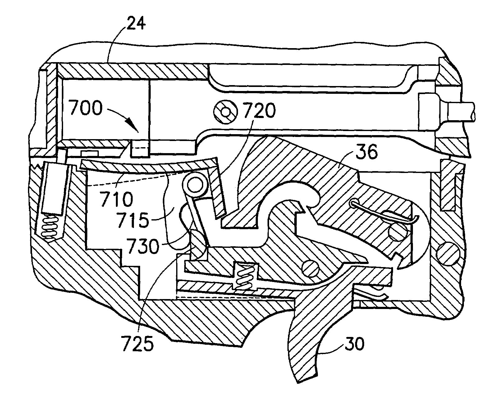
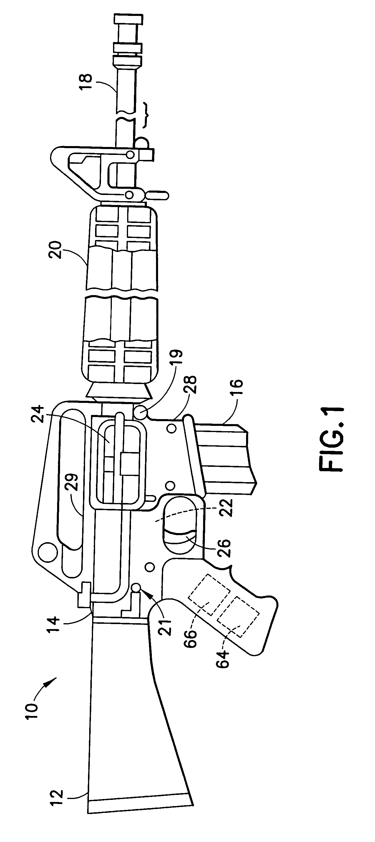
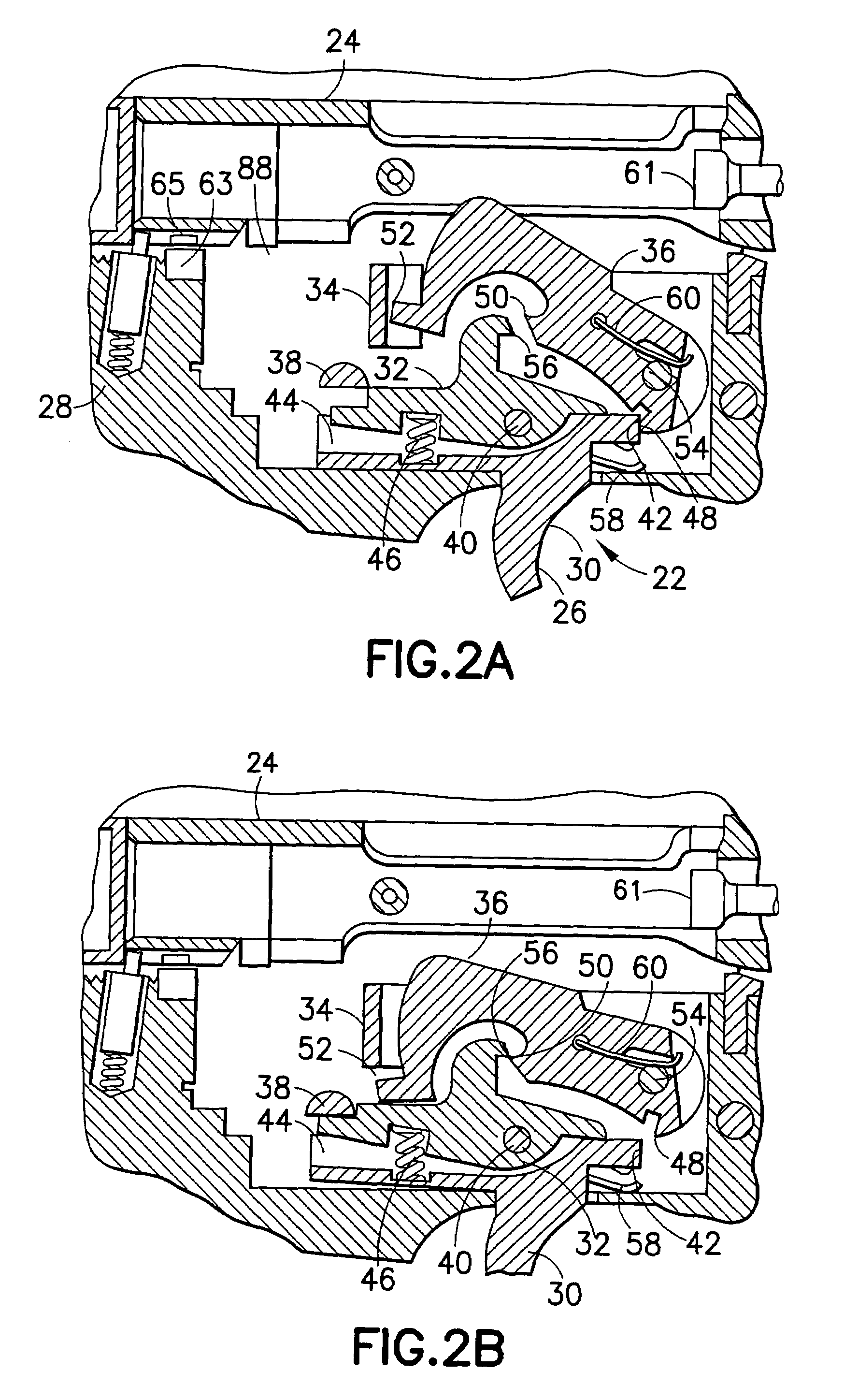
[0026]FIG. 1 shows an elevational side view of a weapon 10 incorporating features of the present invention. The weapon 10 may be similar to an M16 / M4 type of rifle used by the United States Armed Forces. Although the present invention is being described with respect to the embodiment shown in FIG. 1, it should be understood that the present invention can be used with any suitable gas operated, blow back, or other type of firearms including assault weapons, machine guns, and submachine guns. In addition, it should also be understood that the present invention may incorporate any suitable size, shape, or type of elements and suitable type of materials without departing from the spirit of the invention.

[0027]In the embodiment shown in FIG. 1, the weapon 10 may include a stock 12 mounted on a receiver 14. The receiver 14 has a cartridge magazine 16 mounted therein. A barrel 18 is operatively connected to the receiver 14 and has a handgrip 20 mounted thereupon for isolating a user's hand...


PUM


Abstract

A firing mechanism includes a hammer, an electrical solid-state full auto sear positioned to engage the hammer in a first electrical state and to disengage from the hammer in a second electrical state, and a controller connected to the electrical solid-state full auto sear for causing the electrical solid-state full auto sear to change from the first electrical state to the second electrical state. The controller may include circuitry for causing the electrical solid-state full auto sear to change from the first electrical state to the second electrical state at a predetermined rate, a predetermined number of times, or for a predetermined period of time. The hammer may include a retractable hammer bent for engagement with the electrical solid-state full auto sear, and the electrical solid-state full auto sear may include a piezoelectric device.

Description

CROSS-REFERENCE TO RELATED APPLICATION(S)[0001]This application claims the benefit of U.S. Provisional Application No. 60 / 352,132, filed Jan. 23, 2002, which is incorporated by reference herein in its entirety.BACKGROUND OF THE INVENTION[0002]1. Field of the Invention[0003]The present invention relates to controlling the firing of a weapon, and, more particularly, to controlling the firing rate, number of times, and time period of a weapon.[0004]2. Brief Description of Related Developments[0005]Automatic weapons have a known tendency toward reduced control and accuracy when firing in fully automatic mode. This problem is primarily associated with automatic weapons with excessively high rates-of-fire. All weapons experience some degree of muzzle-rise due to recoil. When the rate of full-auto-fire exceeds a certain optimal rate for a particular weapon design, the muzzle no longer has sufficient time to return to the original point of aim between successive rounds, thus causing the wea...

Claims


Application Information

Patent Timeline
Patent Type & Authority Patents(United States)
IPC IPC(8): F41A19/46F41A19/64F41A19/67
CPCF41A19/46F41A19/64F41A19/67
Inventor EALOVEGA, GEORGE D.
Owner CRYSTAL DESIGN
Learn More