
Hearing aid with a radio frequency receiver

a radio frequency receiver and hearing aid technology, applied in the field of hearing aids with radio frequency receivers, can solve the problems of difficult and often even impossible to incorporate a number of crystals corresponding to the desired receiving frequency, difficult and often even impossible to change crystals, etc., and achieve the effect of increasing the number of possible receiving frequencies

Inactive Publication Date: 2005-12-13
OTICON
View PDF10 Cites 8 Cited by
  • Summary
  • Abstract
  • Description
  • Claims
  • Application Information

AI Technical Summary

Benefits of technology

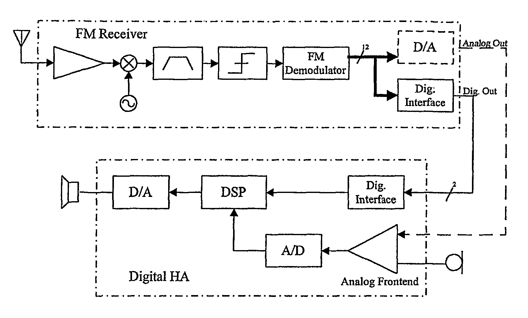
[0010]By integrating the receiver in the hearing aid as defined in claim 3 a possibility of saving space compared to the external device and at the same time provide for multiple frequency selection. The selection means are advantageously integrated in the housing and the possibility of using existing switches and selection means for channel selection is further advantageous.
[0011]By passing the RF signal through the digital interface on the HA, as defined in claim 4, the frontend of the hearing aid can be bypassed. This means that signal-to-noise ratio is not lost in the first critical analog blocks. Besides this, the digital interface increases the flexibility in signal treatment compared to the traditional input parallel to the microphone. The signal level can easily be adjusted to fit the microphone input, and if needed different frequency characteristics can be applied.
[0014]By the embodiment of claim 6 a possibility of passing the RF signal through the digital interface on the hearing aid is obtained, and the frontend of the hearing aid can be bypassed. This provides the same advantages as mentioned above in connection with claim 4.

Problems solved by technology

The very limited space available in such devices makes it difficult and often even impossible to incorporate a number of crystals corresponding to the desired receiving frequencies.
The change of a crystal is rather difficult due to the small size of these elements and the process is rather time consuming.
When however a larger number of frequencies is desired the same problem as described above exists.

Method used


Image

  • Hearing aid with a radio frequency receiver
  • Hearing aid with a radio frequency receiver
  • Hearing aid with a radio frequency receiver

Examples


Embodiment Construction

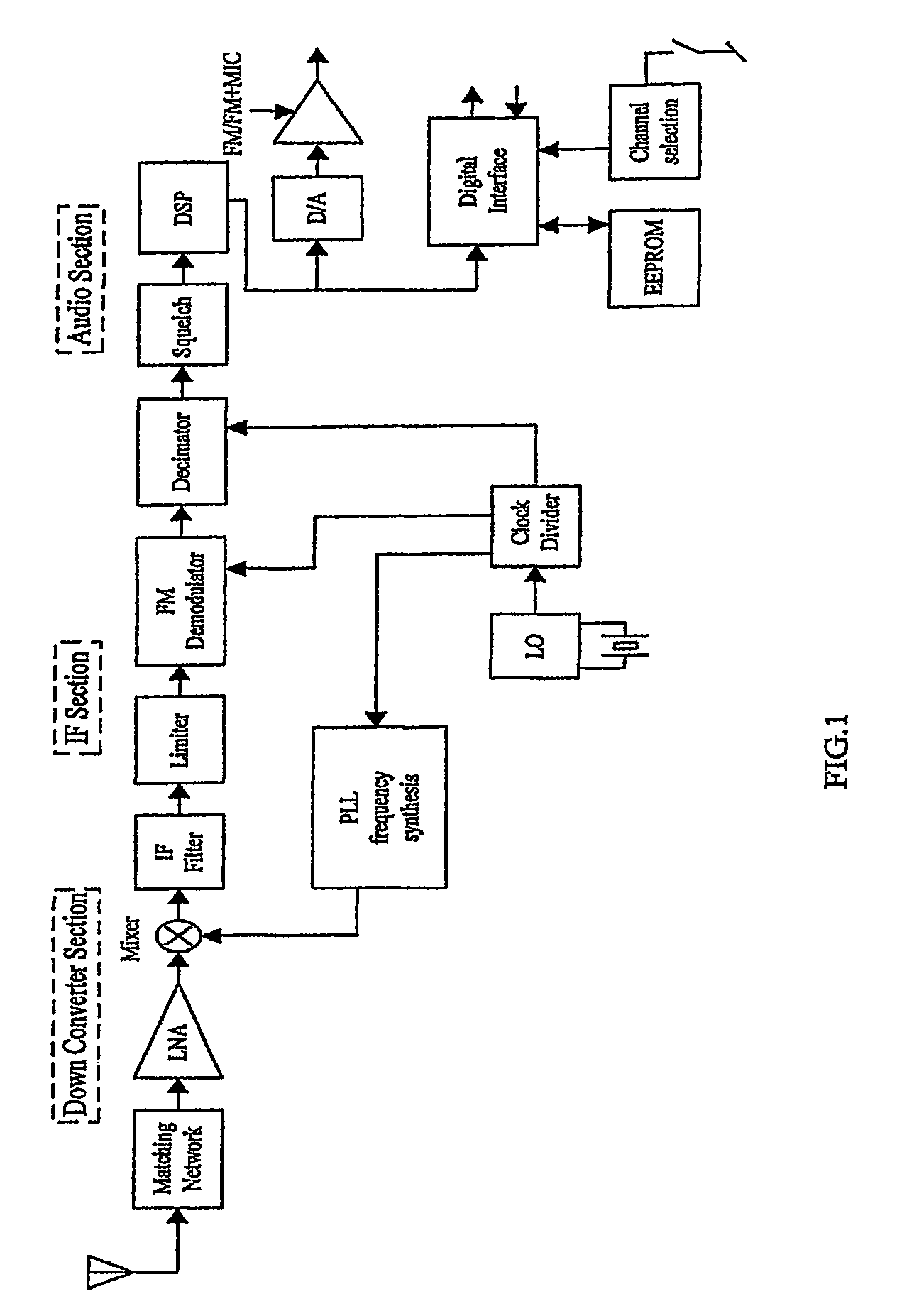
[0021]Referring to FIG. 1 the analog RF signal, preferably a FM signal, is picked up by an antenna, which is connected to the on-chip LNA through an external matching network. The matching network is needed to make the FM receiver flexible towards different types of antennas, and to keep the current consumption down in the LNA.

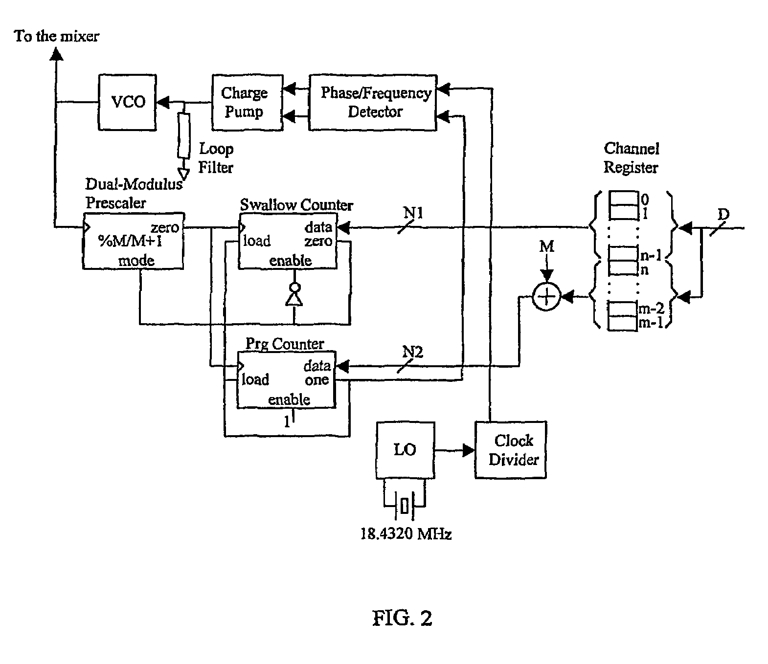
[0022]The LNA (Low Noise Amplifier) is used to amplify the weak signal, which is picked up on the antenna. Low noise is essential due to the low signal level at the input. The LNA wires the signal on to the mixer, which as the second input gets the desired channel frequency from the frequency synthesizer. The frequency synthesis system is described further in connection with FIG. 2.

[0023]The mixer mixes the signal down to an intermediate frequency (IF) of 35 KHz, which is the lowest intermediate frequency acceptable with the given audio bandwidth and frequency deviation. To support the wide range of synthesisable frequencies, the mixer and LNA needs wide opera...


PUM


Abstract

A hearing aid includes a signal path having an input transducer, a processor and an output transducer, the hearing aid further including a radio frequency receiver, where the receiver includes a single crystal oscillator providing a single oscillator frequency and where means are provided for generating a further number of receiving frequencies by transforming the oscillator frequency to the desired receiving frequencies. The hearing aid and the RF receiver may be separate or integrated. The invention further relates to a separate element comprising a RF receiver, the separate element being adapted for mounting on a hearing aid.

Description

AREA OF THE INVENTION[0001]The invention relates to the area of hearing aids comprising a radio frequency receiver. The receiver may be a built in receiver or an external receiver attached to the hearing aid by suitable means.BACKGROUND OF THE INVENTION[0002]It is well known to provide a RF receiver in connection with a hearing aid. Such systems are often used in education situations where a hearing impaired student wearing a hearing aid receives a teachers voice through a RF transmission equipment. Where such systems are used in adjacent classrooms the transmission frequency must be different in the respective classroom in order to ensure receipt of the correct signal by the student.[0003]One example of a hearing aid with a RF receiver is disclosed in CH 641619. The hearing aid with an RF receiver shown in this prior art document and other similar products available on the market today all comprise a single frequency receiving possibility. From U.S. Pat. No. 5,802,183 a further hea...

Claims


Application Information

Patent Timeline
IPC IPC(8): H04R25/00
CPCH04R25/554
Inventor BOGASON, GUDMUNDURKLEMMENSEN, BJARNE
Owner OTICON
Learn More