
System and method for automatically compensating for unbalanced resistance forces

a technology of unbalanced resistance and automatic compensation, which is applied in the field of automatic compensation of unbalanced resistance forces, can solve the problems of residual imbalance and associated vibration, inability to predetermine the rotational resistance force that develops during the use of an orbital sander or other device, and can be particularly high on high-speed machines. , the effect of severe vibration and damag

Inactive Publication Date: 2005-12-13
AB SKF
View PDF18 Cites 35 Cited by
  • Summary
  • Abstract
  • Description
  • Claims
  • Application Information

AI Technical Summary

Benefits of technology

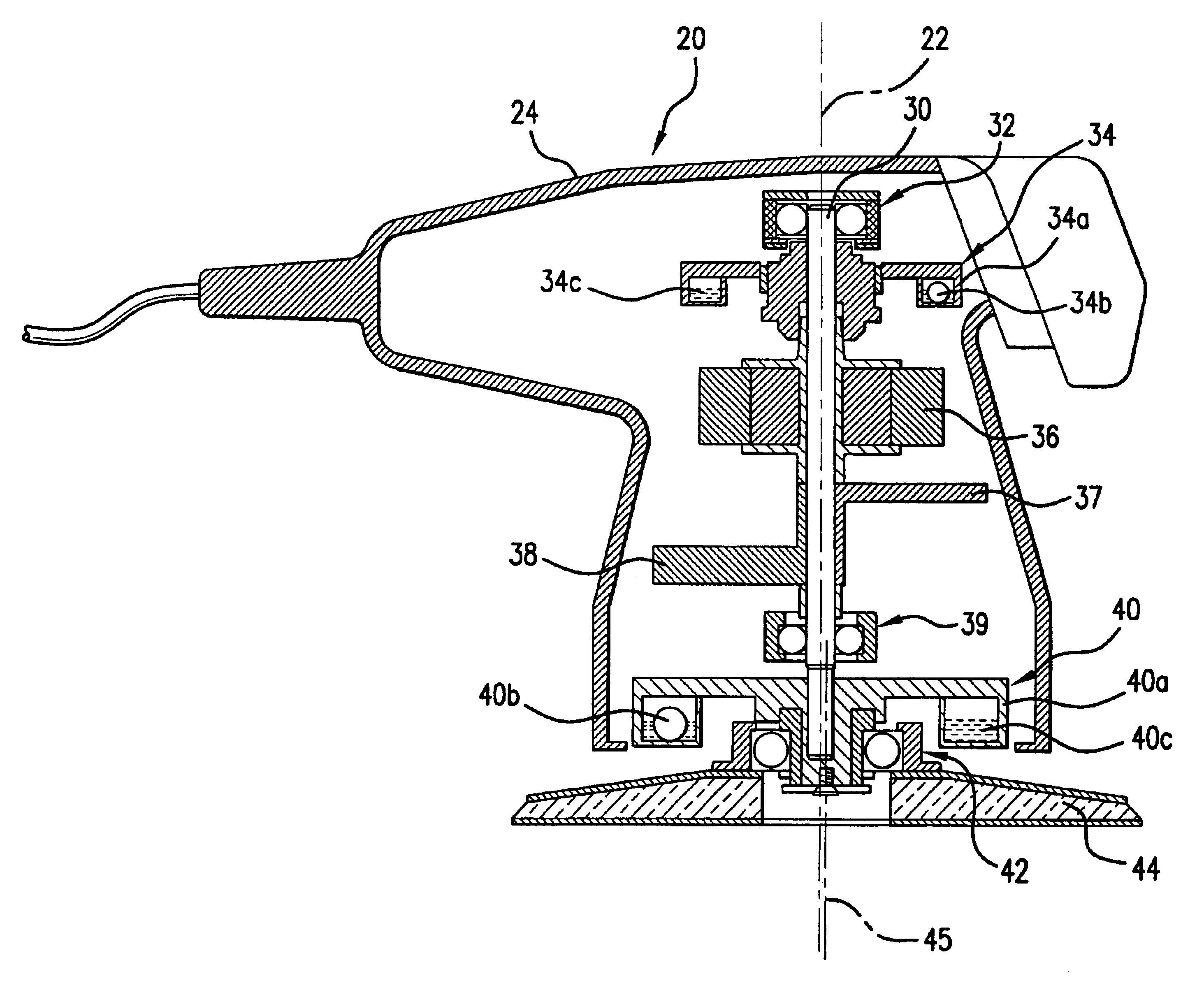
[0007]According to one embodiment of the invention, a device having a rotatable component and automatic or dynamic balancing includes a housing, a shaft rotatably mounted in the housing, the shaft supporting the component near one end of the shaft, at least one counterweight fixedly mounted on the shaft and at least one automatically adjusting balancer mounted on the shaft. The automatically adjusting balancer includes one or more compensating masses contained to move about a path relative to the shaft to compensate for variable imbalanced forces acting on the component.

Problems solved by technology

The rotating resistance forces that develop during the use of an orbital sander or other device cannot be predetermined in advance and tend to change greatly during the operation of the machine.
Accordingly, such balancing inherently leads to residual imbalances and associated vibrations.
These residual vibrations can be particularly high on high-speed machines.
The imbalances which change during operation of the machine, can lead to severe vibrations and damage.

Method used


Image

  • System and method for automatically compensating for unbalanced resistance forces
  • System and method for automatically compensating for unbalanced resistance forces
  • System and method for automatically compensating for unbalanced resistance forces

Examples


Embodiment Construction

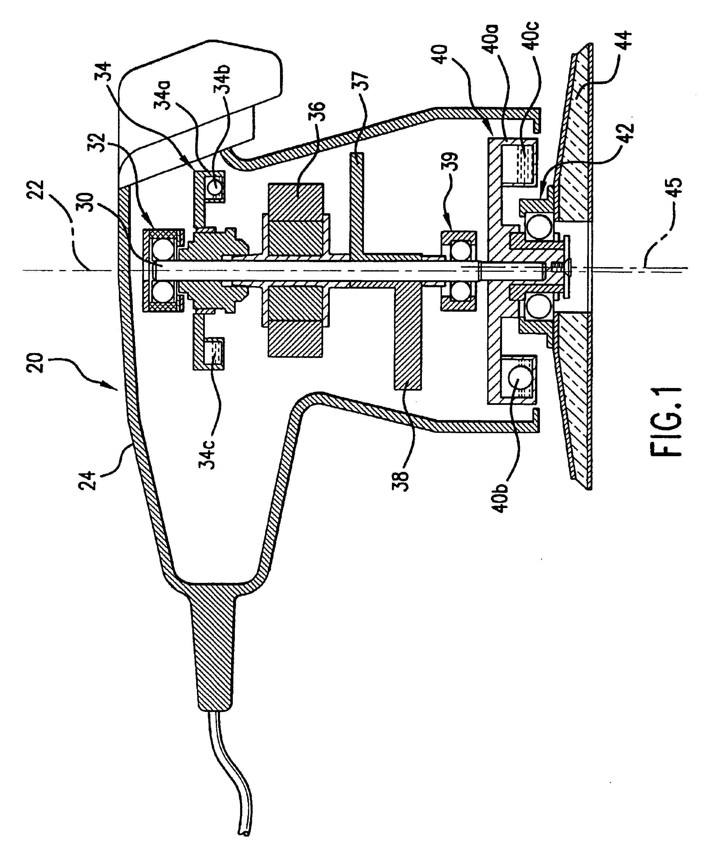
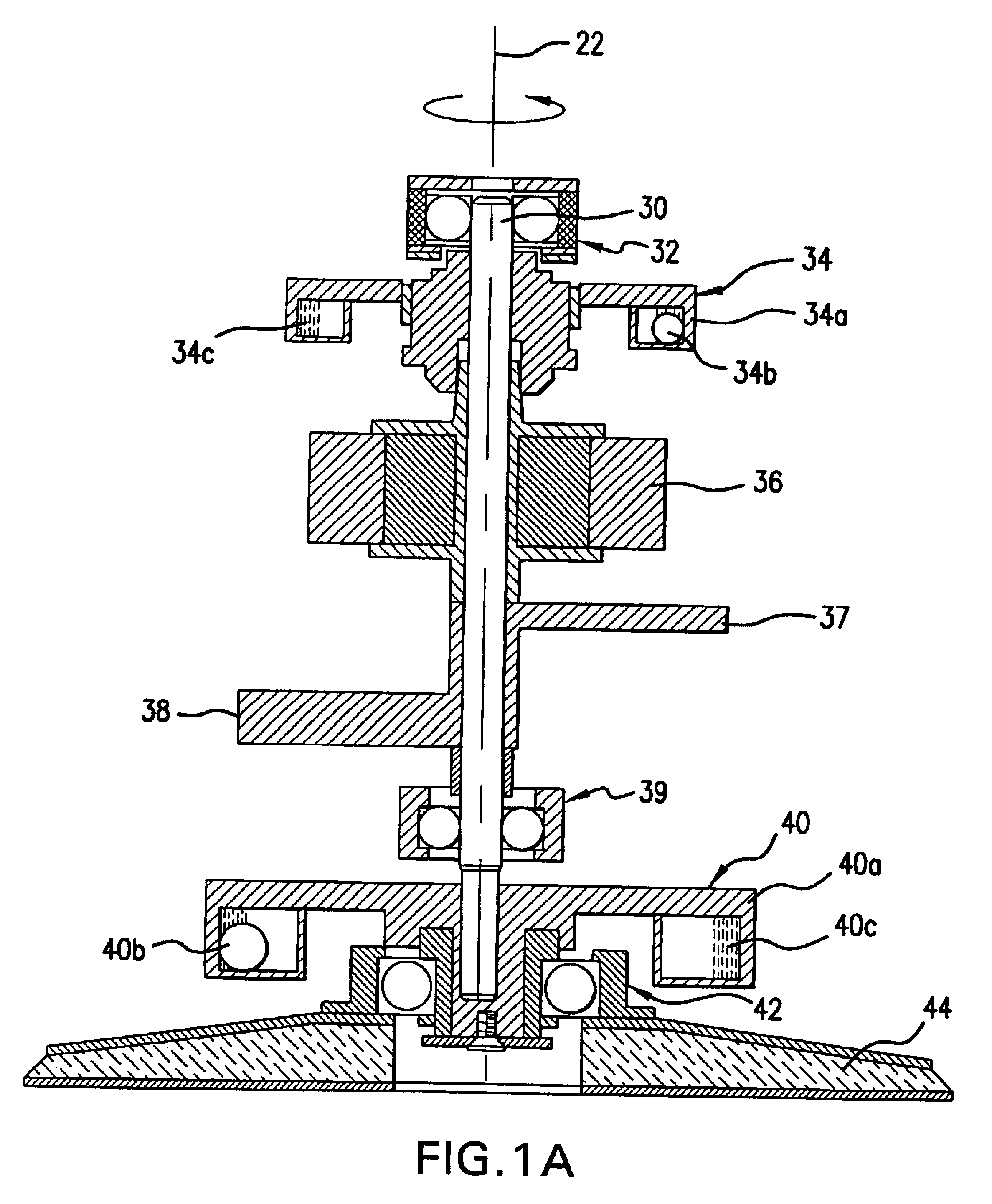
[0039]Referring initially to FIG. 1, an automatic balancing apparatus according to one embodiment of the invention is shown mounted within a housing for an orbital sander 20. The automatic balancing apparatus includes a main central shaft 30 that is rotatably mounted within the housing 24 of the orbital sander 20. An eccentrically mounted sanding pad 44 is mounted at the lower end of the shaft 30, with the axis 45 about which the sanding pad 44 rotates being offset from the central axis 22 of the shaft 30. The shaft 30 is rotatably mounted within an upper bearing 32 and a lower bearing 39, and an additional friction pad bearing 42 rotatably mounts the friction pad 44 eccentrically to the central axis 22 of the shaft 30.

[0040]In the embodiment shown in FIGS. 1, 1A, 1B, and 1C, the central shaft 30 of the automatic balancing apparatus supports an upper automatic balancer 34 and a lower automatic balancer 40 along with a first counterweight 37 and a second counterweight 38. In the embo...


PUM

PropertyMeasurementUnit
Forceaaaaaaaaaa
Frictional forceaaaaaaaaaa

Abstract

A balancing method and apparatus is used for dynamically balancing an out of balance condition in a rotating body caused by resistance forces acting tangentially to the body. A device having a rotatable component and automatic or dynamic balancing includes a housing, a shaft rotatably mounted in the housing, the shaft supporting the component near one end of the shaft, at least one counterweight fixedly mounted on the shaft and at least one automatically adjusting balancer mounted on the shaft. The automatically adjusting balancer includes one or more compensating masses contained to move about a path relative to the shaft to compensate for variable imbalanced forces acting on the component.

Description

[0001]This application claims priority to U.S. Provisional Patent Application No. 60 / 379,765, filed May 14, 2002, the entire disclosure of which is incorporated herein by reference.FIELD OF THE INVENTION[0002]This invention relates to a balancing method and apparatus and, more particularly, to a balancing method and apparatus used for dynamically balancing an out of balance condition in a rotating body caused by resistance forces acting tangentially to the body.BACKGROUND OF THE INVENTION[0003]Many different apparatus for balancing an out of balance condition in a rotating body are known. Such apparatus generally include a counterweight having a weight of a predetermined value which is located at a predetermined position from the axis of rotation to oppose an imbalance in the rotating body. The magnitude of the imbalance is generally known and, accordingly, the necessary weight and position of the counterweight can be calculated so that the weight is positioned where it will act to ...

Claims


Application Information

Patent Timeline
IPC IPC(8): B24B23/02B24B23/04B24B47/12F16F15/28F16F15/31F16F15/32F16F15/36
CPCB24B23/02B24B23/04B24B41/042B24B47/12F16F15/28F16F15/36
Inventor LINDELL, HANSJONSSON, JOAKIMWENDT, VOLKERWIERZBA, PAUL
Owner AB SKF
Learn More