Multi-pole synchronous pulmonary artery radiofrequency ablation catheter
a pulmonary artery and radiofrequency ablation technology, applied in the field of multi-pole synchronous pulmonary artery radiofrequency ablation catheters, can solve the problems of poor therapy efficacy, limited clinical side effects, etc., and achieve the effect of reducing the pressure of the pulmonary artery and successful treatment of pulmonary hypertension
- Summary
- Abstract
- Description
- Claims
- Application Information
AI Technical Summary
Benefits of technology
Problems solved by technology
Method used
Image
Examples
example 1
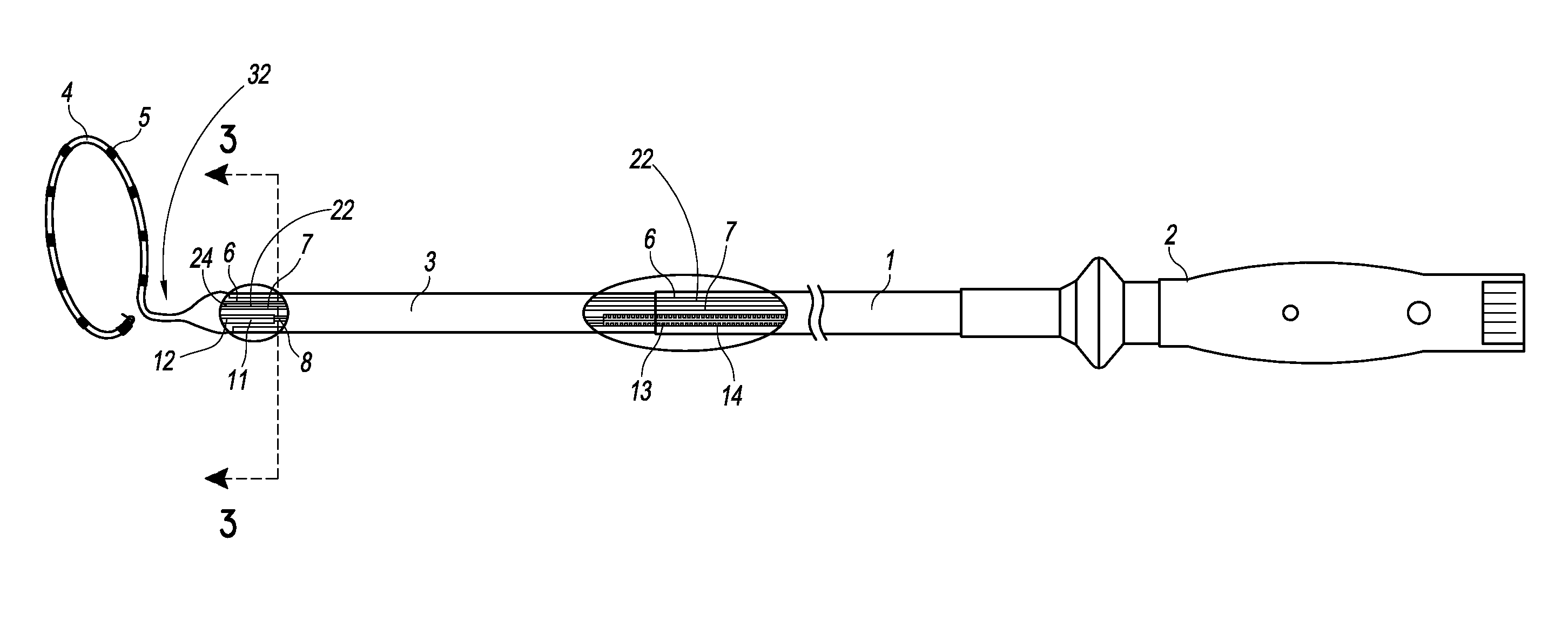
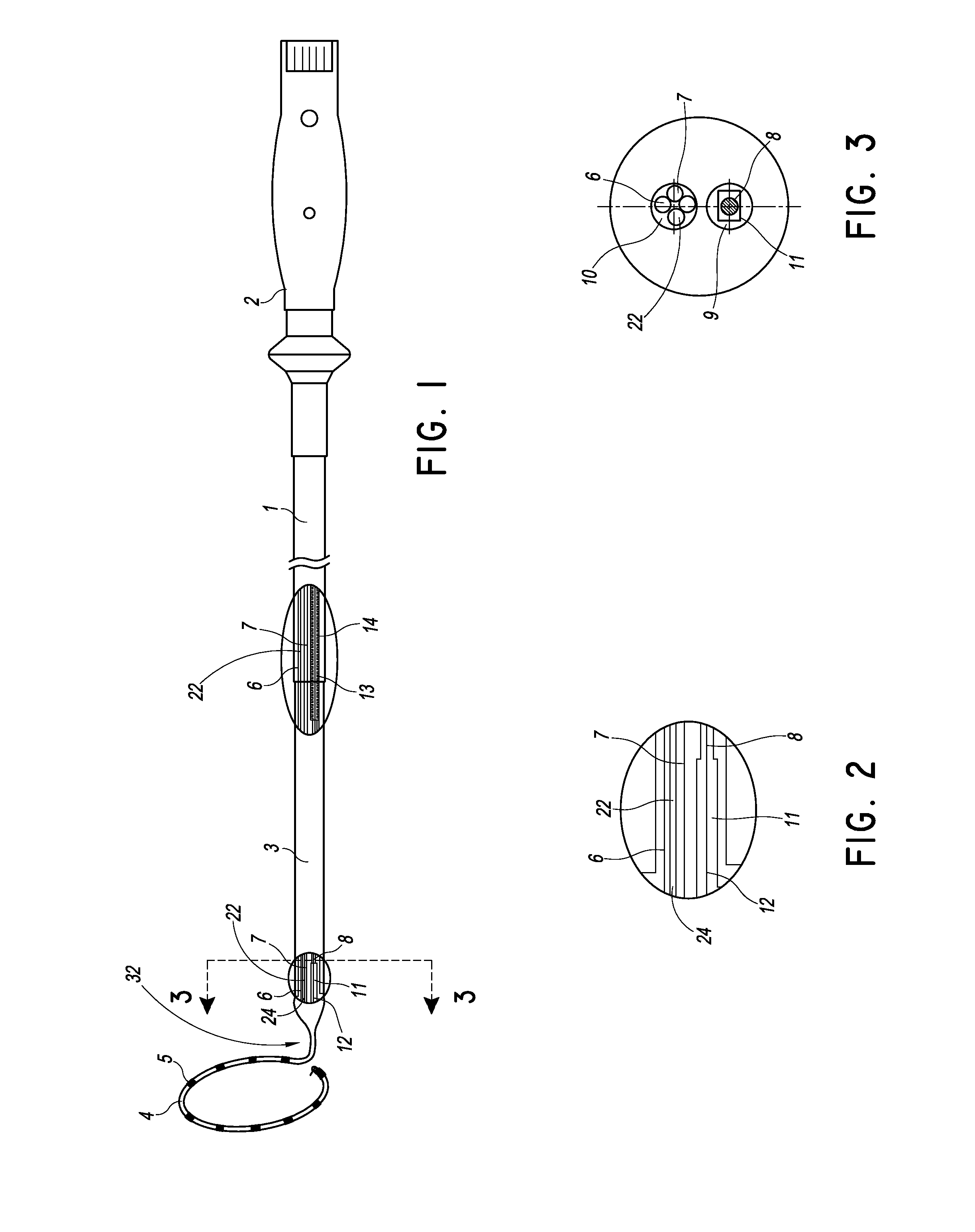
[0104]Through the example below and with reference to FIGS. 1-3, some of the technical solutions that can be achieved by various embodiments are further described below.
[0105]In some embodiments, a multi-pole synchronous pulmonary artery radiofrequency ablation catheter for de-sympathetic ablation in the pulmonary artery can include a catheter body 1 that has a distal end and a proximal end. The distal end can be provided with a flexible end 3 and the proximal end can be provided with a control handle 2. A pull wire can extend in the catheter body.
[0106]Preferably, the catheter body can be made of a polymer material, which is a poor heat conductor, so that it can avoid transmitting or reducing the amount of heat transferred from the electrodes to the blood flow contacting the catheter body, and thereby can better prevent the electrode from heating the blood flow.
[0107]The flexible end 3 can include a proximal end and a distal end. An annular ring 4 can be arranged on the distal end....
example 2
Example 2
[0126]A multi-pole synchronous pulmonary artery radiofrequency ablation catheter comprises a control handle 2, a catheter body 1, and an annular ring 4. The control handle 2 can be provided with an adjustment apparatus, the catheter body 1 can be hollow, and a cavity can be arranged in the catheter body 1. One or more lead wires 6, temperature sensing wires 7, and a pull wire 8 can be arranged in cavity.
[0127]One end of catheter body can be flexible, and the flexible end 3 can be connected to the annular ring 4. The other end of the catheter body can be connected to the control handle 2. One end of the pull wire 8 can be connected to the flexible end 3, and the other end of the pull wire 8 can be connected to the adjustment apparatus of the control handle, and the adjustment apparatus adjusts the tension of the pull wire 3 to control the curvature of the flexible end. This allows the operator to control the handle with one hand and adjust the curvature of the flexible end ...
example 3
Example 3
[0136]Example 3 is similar to Example 1 and Example 2, and the differences can include an infusion tube 22 arranged in the catheter body, a group of evenly distributed through holes 15 (FIG. 4) arranged on one or more of the electrodes 5, with a bore diameter of 1 μm. One end of the infusion tube 22 can be connected to the electrodes 5 through the annular ring 4 such that fluid diffuses out from the through holes 15 on each of the electrodes 5. For example, the annular ring 4 can include or define at least one lumen 24 extending between a proximal end of the annular ring 4 and to the through holes 15 so as to form a closed fluidic connection. In such embodiments, a distal end of the infusion tube 22 can be connected to the proximal end of the lumen 24 in the annular ring 4. The other end of the infusion tube 22 can be connected to a transfusion system, such as a constant-flux pump or other known pumps.
[0137]When electrodes 5 generate current, the liquid automatically diff...
PUM
 Abstract
Description
Claims
Application Information
 - R&D
- Intellectual Property
- Life Sciences
- Materials
- Tech Scout
- Unparalleled Data Quality
- Higher Quality Content
- 60% Fewer Hallucinations
Browse by: Latest US Patents, China's latest patents, Technical Efficacy Thesaurus, Application Domain, Technology Topic, Popular Technical Reports.
© 2025 PatSnap. All rights reserved.Legal|Privacy policy|Modern Slavery Act Transparency Statement|Sitemap|About US| Contact US: help@patsnap.com


