
Data storage system having atomic memory operation

Active Publication Date: 2005-12-06
EMC IP HLDG CO LLC
View PDF3 Cites 61 Cited by
  • Summary
  • Abstract
  • Description
  • Claims
  • Application Information

AI Technical Summary

Benefits of technology

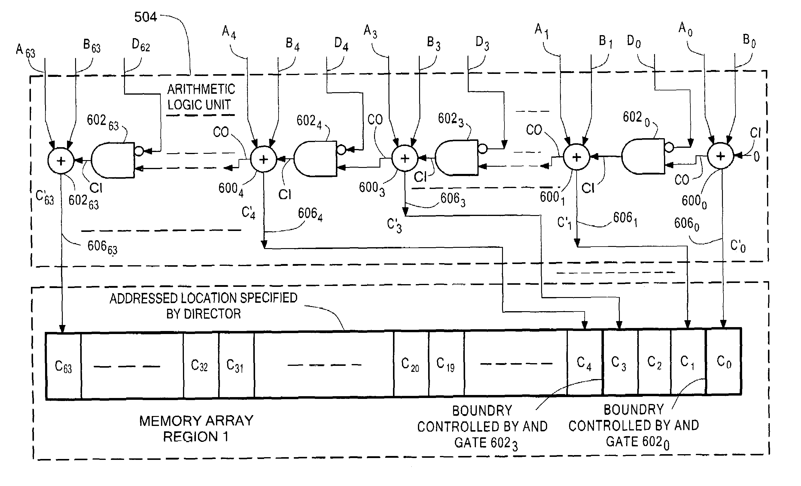
[0015]In accordance with another feature of the invention, a read-modify-write system is provided. The section includes: (a) a memory; (b) a write buffer for receiving data, such data comprising: plural bit write data; and plural bit carry bit mask data; (c) a read buffer for receiving plural bit data read from the memory, such read buffer providing such plural bit data read from the memory at an address; and (d) an arithmetic unit fed by: the plural bit write data and the plural bit carry bit mask data received in the write buffer; and, the plural bit data read from the memory and received by the read buffer. The arithmetic unit comprising: a plurality of successively arranged full adder sections, each one of such full adder sections having: a pair of data bit inputs; and a carry bit input. The pair of data bit inputs are coupled to a corresponding

Problems solved by technology

Such technique however that all other locations in the memory becoming inaccessible for other operations by other users of the memory.

Method used


Image

  • Data storage system having atomic memory operation
  • Data storage system having atomic memory operation
  • Data storage system having atomic memory operation

Examples


Embodiment Construction

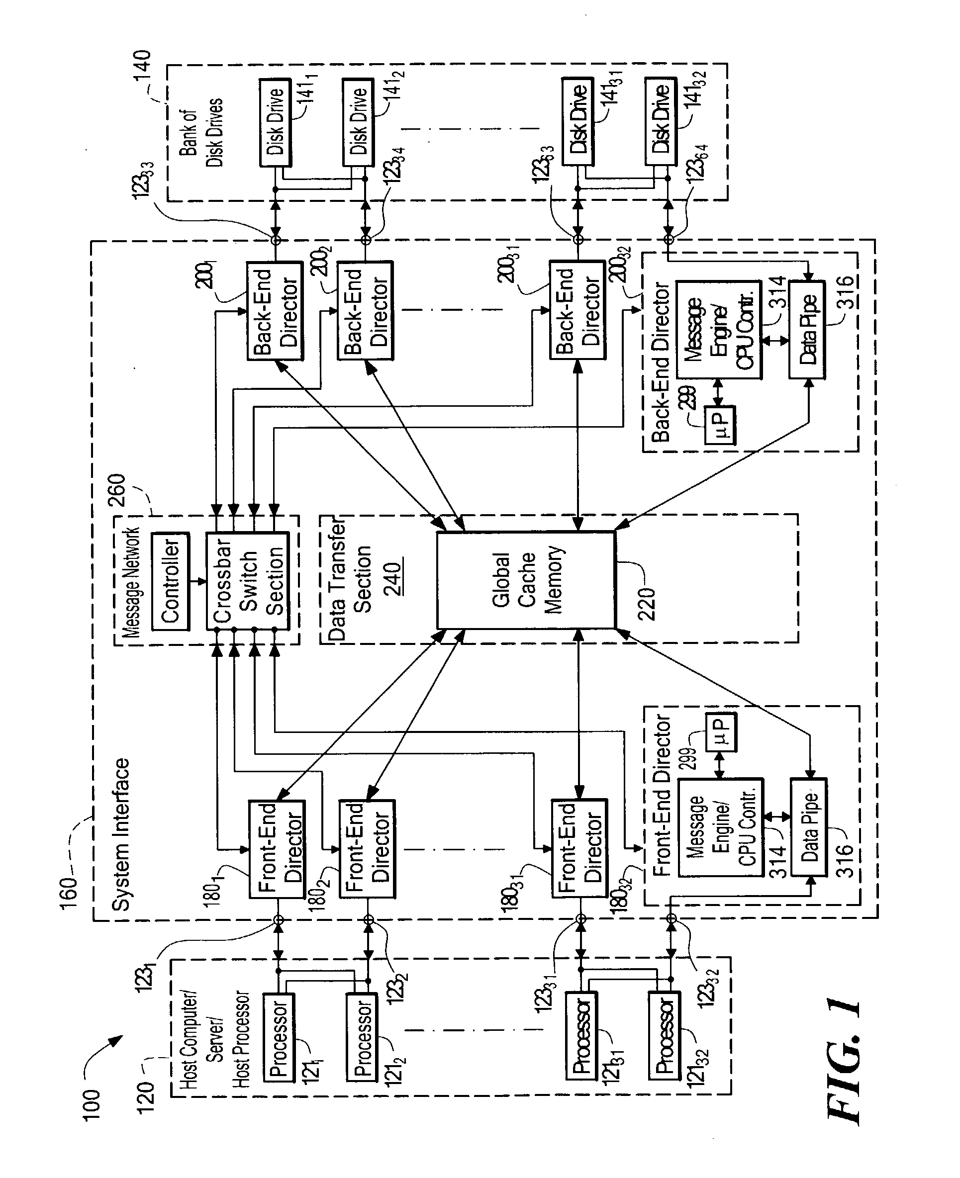
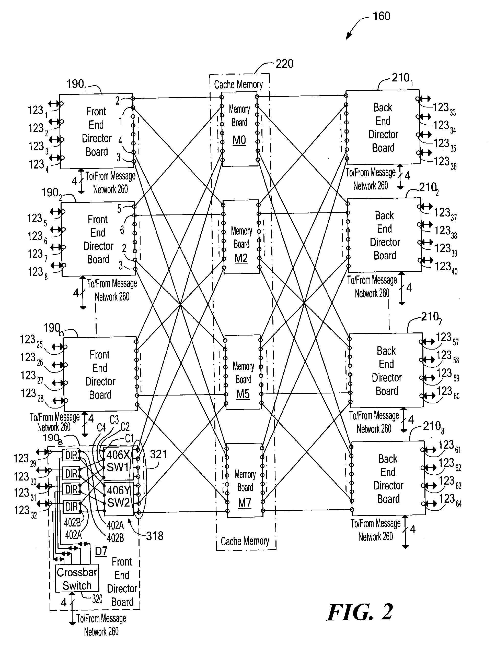
[0025]Referring now to FIG. 1, a data storage system 100 is shown for transferring data between a host computer / server 120 and a bank of disk drives 140 through a system interface 160. The system interface 160 includes: a plurality of, here 32 front-end directors (sometimes referred to as processors or controllers) 1801–18032 coupled to the host computer / server 120 via ports 1231–12332; a plurality of back-end directors 2001–20032 coupled to the bank of disk drives 140 via ports 12333–12364; a data transfer section 240, having a global cache memory 220, coupled to the plurality of front-end directors 1801–18016 and the back-end directors 2001–20016; and a messaging network 260, operative independently of the data transfer section 240, coupled to the plurality of front-end directors 1801–18032 and the plurality of back-end directors 2001–20032, as shown. The front-end and back-end directors 1801–18032, 2001–20032 are functionally similar and include a microprocessor (μP) 299 (i.e., a...


PUM


Abstract

A method and system for enabling a director to perform an atomic read-modify-write operation on plural bit read data stored in a selected one of a plurality of memory locations. The method includes providing a plurality of successive full adders, each one of the full adders being associated with a corresponding one of the bits of the plural bit read data. Each one of the full adders has a summation output, a carry bit input and a carry bit output. The method includes adding in each one of the full adders: (a) a corresponding bit of plural bit input data provided by the director; (b) the corresponding one of the bits of the plural bit read data; and, (c) a carry bit fed the carry bit input from a preceding full adder. Each one of the full adders provides: (a) a carry bit on the carry output thereof representative of the most significant bit produced by the full adder; and, (b) a bit on the summation output representative of a least significant bit produced by the full adder. The bit on the summation output is stored in a corresponding bit location in the selected one of a plurality of memory locations. The method selectively couples, or inhibits coupling, the carry bit produced from one of the full adders to the carry bit input of a next successive full adder selectively in accordance with a corresponding bit of a plural bit carry bit mask provided by the director providing a full adder for each one of the bits of the plural bit read stored. The full adder has a carry bit input and a carry bit output. The method includes adding each one of a bits of plural bit input data provided by the director with a corresponding one of the bits of the plural bit read data in the provided full adder together with a carry bit fed the carry bit input of such provided full adder. The full adder provides: a carry output bit; and, a summation of the bits fed to such provided full adder to the corresponding bit location in the selected one of a plurality of memory locations. The method selectively couples, or inhibits coupling, a carry bit produced by one full adder provided for a lower order bit of the plural bit read data to the carry bit input of a second full adder provided by for next, successive higher order bit of the plural bit read data selectively in accordance with one of a plurality of bits of a carry bit mask provided by the director.

Description

INCORPORATION BY REFERENCE[0001]This application incorporates by reference, in their entirety, the following co-pending patent applications all assigned to the same assignee as the present invention:[0002]FILINGSer.INVENTORSDATENo.TITLEYuval Ofek et al.Mar. 31, 200009 / 540,828Data Storage SystemHaving Separate DataTransfer Section AndMessage NetworkPaul C. Wilson etJun. 29, 200009 / 606,730Data Storage Systemal.Having Point-To-PointConfigurationJohn K. Walton etJan. 22, 200210 / 054,241Data Storage Systemal.(Divisional of09 / 223,519 filedDec. 30, 1998)Christopher S.Dec. 21, 200009 / 745,859Data Storage SystemMacLellan et al.Having Plural FaultDomainsJohn K. WaltonMay 17, 200109 / 859,659Data Storage SystemHaving No-OperationCommandTECHNICAL FIELD[0003]This invention relates generally to data storage systems, and more particularly to data storage systems having atomic memory operations.BACKGROUND[0004]As is known in the art, large host computers and servers (collectively referred to herein as ...

Claims


Application Information

Patent Timeline
IPC IPC(8): G06F12/00
CPCG06F9/30014G06F9/3004
Inventor WALTON, JOHN K.
Owner EMC IP HLDG CO LLC
Learn More