Method and circuit for correcting periodic signals of an incremental position measuring system

a technology of incremental position and periodic signal, which is applied in the direction of pulse characteristics measurement, pulse technique, instruments, etc., can solve the problems of insufficient space, complex circuit arrangement, and insufficient accuracy of incremental position measurement system, and achieve not inconsiderable amount of required space disadvantage, not ideal signal shape, and high cos

Inactive Publication Date: 2005-12-06
DR JOHANNES HEIDENHAIN GMBH
View PDF39 Cites 8 Cited by
  • Summary
  • Abstract
  • Description
  • Claims
  • Application Information

AI Technical Summary

Benefits of technology

[0015]It is moreover an object of the present invention to disclose a circuit arrangement for correcting periodic signals of an incremental position measuring system, which can be provided as cost-effectively and compactly as possible.
[0017]The method in accordance with the present invention has the advantage that both minor, as well as strong, fluctuations of signal parameters of the periodic signals from the position measuring system, for example amplitude fluctuations of various strengths, are corrected without overshooting. Minimal fluctuations of the signal parameter signal amplitude can be caused during the normal measuring operation by normal drifting processes, for example, while strong amplitude fluctuations are caused by the soiling of the scanned measuring graduation. In both cases, the method in accordance with the present invention assures the dependable correction of the signals transmitted to the sequential electronic device.
[0018]The circuit arrangement in accordance with the present invention has the advantage that it is possible to control slow fluctuations, as well as rapid fluctuations in the signals, for example of the signal parameter signal amplitude, with only one circuit arrangement.
[0019]A further advantage lies in the insensitivity of the circuit arrangement in accordance with the present invention in regard to interferences which are superimposed on the signals of the position measuring system. In the case of an amplitude correction this is achieved in that the amplitude of the signals from the position measuring systems is observed over only a very short period of time in order to subsequently correct a possibly existing error. All interferences which are not contained in this time interval cannot affect the correction, or control.
[0021]It should furthermore be mentioned, that the circuit arrangement in accordance with the present invention requires only a small circuitry outlay, but that at the same time a rapid and dependable signal correction is assured. The circuit arrangement in accordance with the present invention does not require the detection of peak signal values in particular, which makes great demands on circuit technology.

Problems solved by technology

However, as a rule the respective position measuring system does not produce such an ideal signal shape, i.e. because of the most diverse reasons the generated signals usually contain errors with regard to the signal parameters signal amplitude, signal offset and phase position of the signal.
The disadvantage in this lies in that a relatively complex, and therefore expensive circuit arrangement, in particular a separate processor, is required for performing the three correction steps.
Besides the expenses, the not inconsiderable amount of required space is disadvantageous, since the circuit arrangement is advantageously arranged directly on the measuring system.
The disadvantage here again lies in the requirement of a processor for determining the optimum values.
Furthermore, the optimum values are calculated only for defined positions and are not permanently readjusted, because of which suboptimal values are unavoidably being set.
The disadvantage of this arrangement is that only a one-stage control is possible.
Therefore either a wide amplitude fluctuation of one of the sinusoidal signals cannot be corrected quickly enough or, with a narrow amplitude fluctuation, overshooting of the control cannot be prevented.
Moreover, a regulating device is required which, as a rule, is provided by a processor, which represents a considerable monetary outlay and has a considerable space requirement.

Method used


Image

  • Method and circuit for correcting periodic signals of an incremental position measuring system
  • Method and circuit for correcting periodic signals of an incremental position measuring system
  • Method and circuit for correcting periodic signals of an incremental position measuring system

Examples


Embodiment Construction

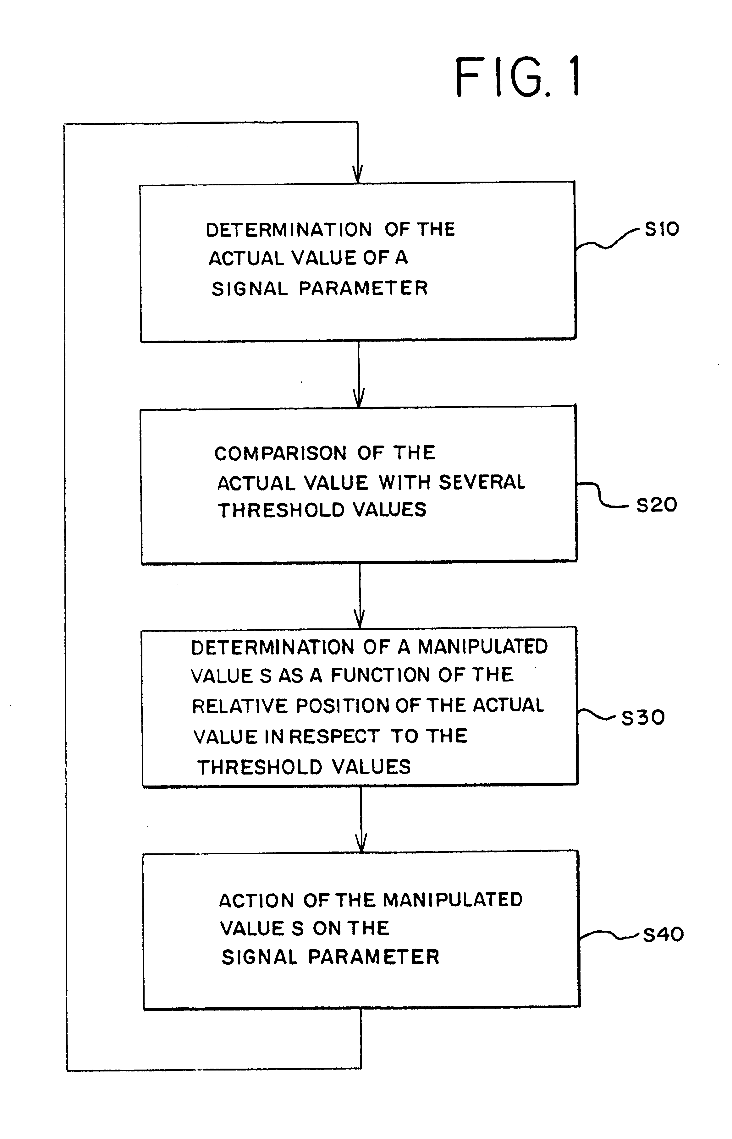
[0031]The basics of the method in accordance with the present invention will be explained in what follows with the aid of the flow diagram in FIG. 1. The basis of the described method is considered to be an incremental position measuring system, including a periodic measuring graduation and a scanning unit which is movable with respect to it. The result of a relative movement between the measuring graduation and the scanning unit are periodic signals which are modulated as a function of the displacement and are transmitted to a downstream connected sequential electronic device. Here, the relative movement can be provided in the form of a linear movement, as well as in the form of a rotational movement.

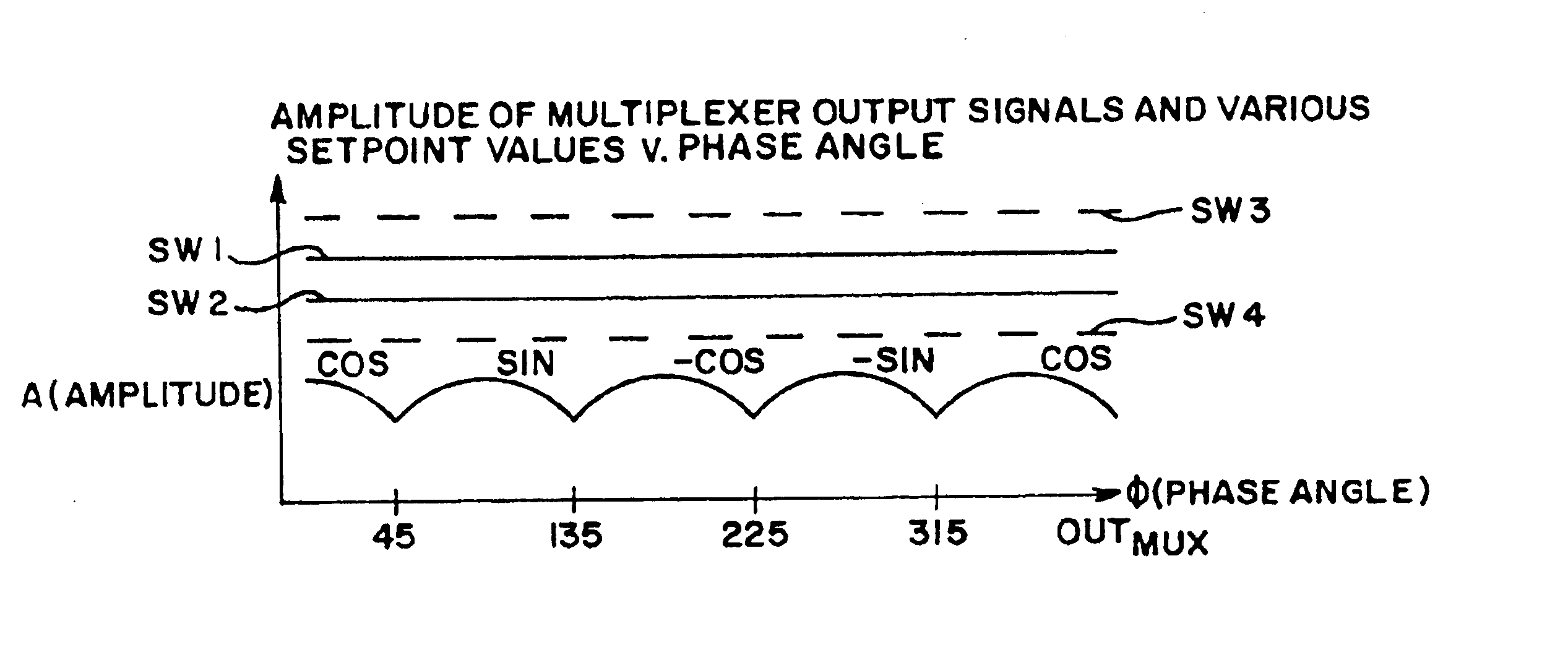
[0032]The signals generated are customarily a pair of sinusoidal analog signals with a phase shift of 90° with respect to each other. Such a position measuring system can be employed, for example, for the precise determination of the relative position of a tool and a workpiece in a num...


PUM


Abstract

A circuit arrangement for the correction of periodic signals from an incremental position measuring system that includes a first assembly comprising a multiplexer having an input to which a periodic signal is supplied and an output out of which an output signal is transmitted, a second assembly that receives the output signal and compares the output signal with at least one preset threshold value and, the second assembly selects a manipulated variable as a function of an actual position of a signal parameter in relation to the at least one preset threshold value from at least two preset, different manipulated variables and an actuating member that performs an action on the signal parameter in order to adjust the signal parameter in a direction toward a preset setpoint value.

Description

[0001]Applicants claim, under 35 U.S.C. §§120 and 365, the benefit of priority of the filing date of Mar. 22, 2000 of a Patent Cooperation Treaty patent application, copy attached, Ser. No. PCT / EP00 / 02576, filed on the aforementioned date, the entire contents of which are incorporated herein by reference.[0002]Applicants claim, under 35 U.S.C. § 119, the benefit of priority of the filing date of Mar. 30, 1999 of a German patent application, copy attached, Ser. No. 199 14 388.9, filed on the aforementioned date, the entire contents of which are incorporated herein by reference.BACKGROUND OF THE INVENTION[0003]1. Field of the Invention[0004]The present invention relates to a method, as well as a circuit arrangement for correcting periodic signals from an incremental position measuring system.[0005]2. Description of the Related Art[0006]A circuit arrangement for correcting sinusoidal signals containing position information is known from EP 708 311 A2. In this case, the dc components, t...

Claims


Application Information

Patent Timeline
Patent Type & Authority Patents(United States)
IPC IPC(8): G01D5/245G01B7/00G01D3/032G01D5/244G01R35/00H03H11/02
CPCG01D5/24476G01D5/2448
Inventor BURGSCHAT, REINERKRAUSS, MATHIAS
Owner DR JOHANNES HEIDENHAIN GMBH
Why Eureka
Try Eureka