
Spinning reel rotor braking device

a rotor braking and spinning reel technology, applied in fishing, reels, applications, etc., can solve the problem of difficult contact between the braking member and the very small stepped portion, and achieve the effect of stabilizing the braking for

Active Publication Date: 2005-12-06
SHIMANO INC
View PDF6 Cites 5 Cited by
  • Summary
  • Abstract
  • Description
  • Claims
  • Application Information

AI Technical Summary

Benefits of technology

[0013]A purpose of the present invention is to stabilize the braking force of a rotor braking device in a spinning reel.
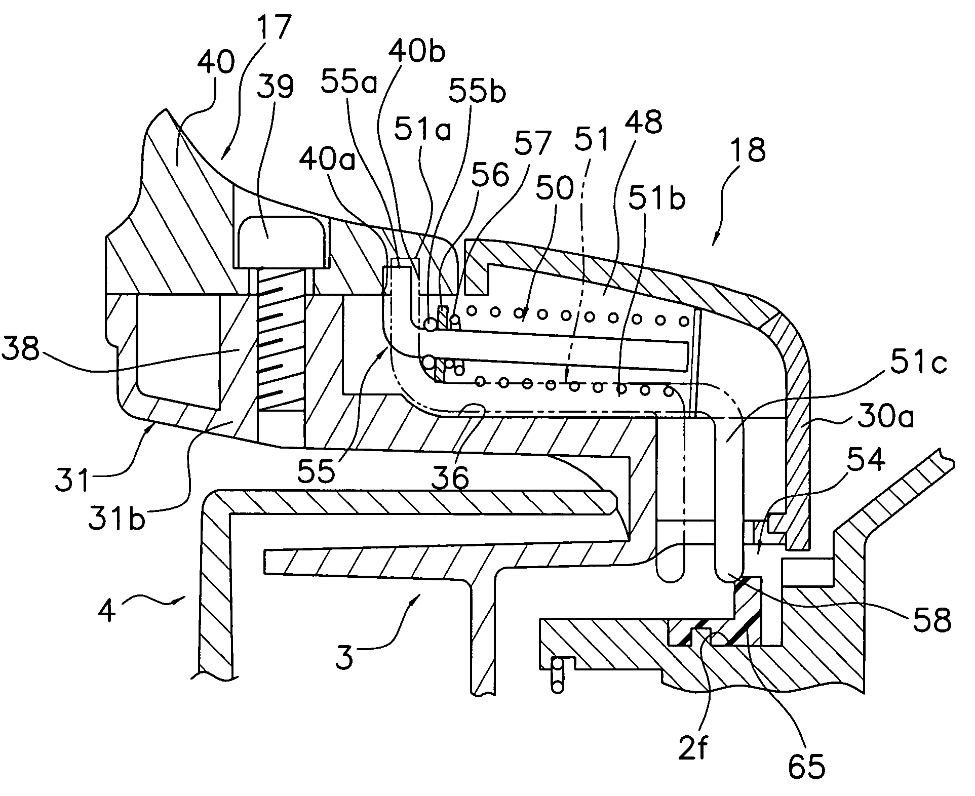
[0015]This rotor braking device has a restriction mechanism that restricts the backward movement of the braking member so that the braking member does not come into contact with the rear end of the mounting groove. Here, because the restriction mechanism protects the braking member from coming into contact with the rear end of the mounting groove, even if a very small stepped portion is formed on the rear end portion of the mounting groove, it will be difficult for the braking member to come into contact with the very small stepped portion. Accordingly, a predetermined braking force can be obtained and thus the braking force can be stabilized because the braking member will no longer move and the braking force will no longer change.
[0016]The rotor braking device of the spinning reel according to the second aspect of the present invention is the device disclosed in the first aspect of the present invention, in which the braking member further includes an engaging portion that unrotatably engages with the protruding portion of the moving member when the moving member is moved to the second position. The drag portion frictionally slides against the mounting groove of the reel unit when the protruding portion of the moving member engages with the engaging portions. Here, because the drag portion rotatably and frictionally engages with the mounting groove, the rotor is not braked only on one portion as in the prior art, but is uniformly braked over the entire drag portion, and thus the braking force can be stabilized.
[0019]The rotor braking device of the spinning reel according to the fifth aspect of the present invention is the device disclosed in the first aspect of the present invention, in which the drag portion frictionally slides against the protruding portion of the moving member when the moving member is in the second position. Here, because the protruding portion of the moving member directly contacts the drag portion, a braking force can be easily obtained and the structure of the braking member can be simplified.
[0021]The rotor braking device of the spinning reel according to the seventh aspect of the present invention is the device disclosed in any of the first through sixth aspects of the present invention, in which the restriction mechanism includes an interlocking groove that is formed on the inner periphery of the braking member, and an interlocking protrusion that is formed on the outer periphery of the mounting groove and capable of interlocking with the interlocking groove. Here, by interlocking the interlocking protrusion of the mounting groove with the interlocking groove of the braking member, rearward movement of the braking member can be restricted.
[0022]The rotor braking device of the spinning reel according to the eighth aspect of the present invention is the device disclosed in any of the first through sixth aspects of the present invention, in which the restriction mechanism includes an interlocking protrusion that is formed on the inner periphery of the braking member, and an interlocking groove that is formed on the outer periphery of the mounting groove and capable of interlocking with the interlocking protrusion. Here, by interlocking the interlocking protrusion of the braking member with the interlocking groove of the mounting groove, rearward movement of the braking member can be restricted.

Problems solved by technology

Here, because the restriction mechanism protects the braking member from coming into contact with the rear end of the mounting groove, even if a very small stepped portion is formed on the rear end portion of the mounting groove, it will be difficult for the braking member to come into contact with the very small stepped portion.

Method used


Image

  • Spinning reel rotor braking device
  • Spinning reel rotor braking device
  • Spinning reel rotor braking device

Examples


Embodiment Construction

[0043]Selected embodiments of the present invention will now be explained with reference to the drawings. It will be apparent to those skilled in the art from this disclosure that the following descriptions of the embodiments of the present invention are provided for illustration only and not for the purpose of limiting the invention as defined by the appended claims and their equivalents.

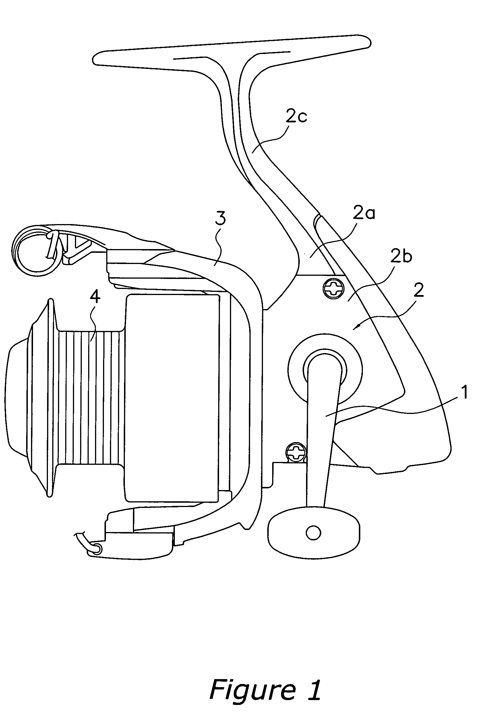
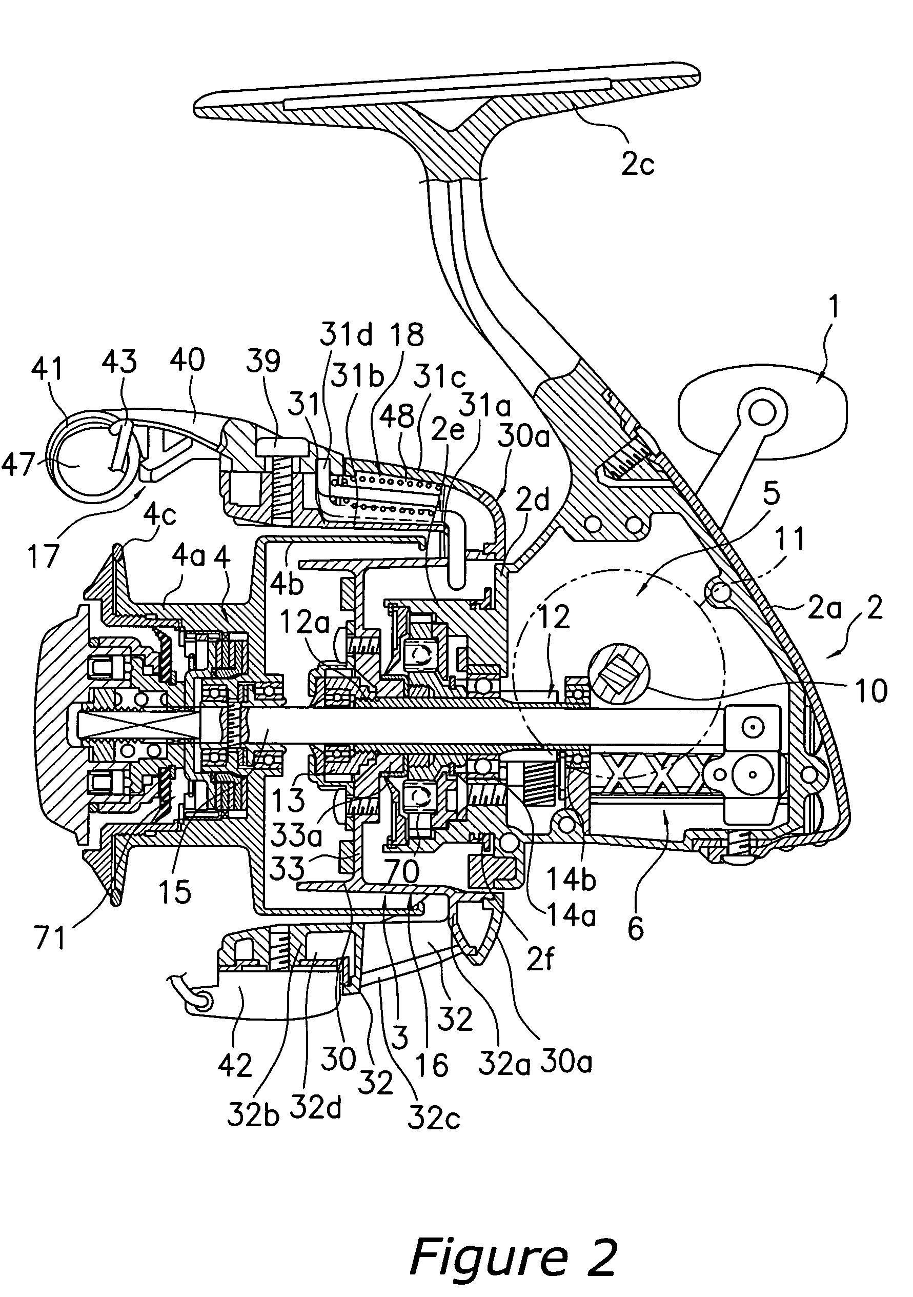
[0044]As shown in FIGS. 1 and 2, a spinning reel in which an embodiment of the present invention is applied includes a handle 1, a reel unit 2 that rotatably supports the handle 1, a rotor 3, and a spool 4. The rotor 3 is rotatively supported on the front of the reel unit 2. The spool 4 is for winding fishing line around the outer peripheral surface, and is arranged at the front end of the rotor 3 so that it can be shifted back and forth. Note that the handle 1 is mounted on the left side of the reel unit 2 in FIG. 1, and on the right side thereof in FIG. 2. Thus, the handle 1 can be mounted on eit...


PUM


Abstract

A spinning reel rotor braking device has a moving member, a braking member, and a restriction mechanism. The moving member is provided on the rotor and movable between a first position and a second position as the bail arm moves. The braking member is mounted on the mounting groove of the reel unit, and has a drag portion that generates a braking force by frictionally sliding against the moving member when the moving member is in the second position. The restriction mechanism is formed on an inner periphery of the braking member and on an outer periphery of the mounting groove, and restricts backward movement of the braking member relative to the reel unit so that the braking member does not come into contact with a rear end portion of the mounting groove. With the present invention, the braking force of the rotor braking device can be stabilized.

Description

BACKGROUND OF THE INVENTION[0001]1. Field of the Invention[0002]The present invention generally relates to a rotor braking device. More specifically, the present invention relates to a spinning reel rotor braking device for a spinning reel that brakes a rotor rotatably mounted on a reel unit of the spinning reel in response to the pivoting of a bail arm that pivots between a line-winding posture and a line-releasing posture.[0003]2. Background Information[0004]A rotor on a spinning reel is generally provided with a bail arm for guiding fishing line to a spool. The bail arm can assume a line-winding posture, in which the fishing line is guided to the circumference of the spool when winding up the fishing line, and a line-releasing posture, in which the bail arm is toppled over from the line-winding posture so that it does not pose a hindrance when the fishing line is rolled off from the spool. The rotor is provided with a bail tripping device, which maintains the bail arm in the line...

Claims


Application Information

Patent Timeline
Patent Type & Authority Patents(United States)
IPC IPC(8): A01K89/02A01K89/01
CPCA01K89/0108A01K89/01A01K89/02
Inventor SUGAWARA, KEN'ICHI
Owner SHIMANO INC
Learn More