
Method and device for downlink packet switching

Inactive Publication Date: 2005-11-29
RPX CORP
View PDF10 Cites 53 Cited by
  • Summary
  • Abstract
  • Description
  • Claims
  • Application Information

AI Technical Summary

Benefits of technology

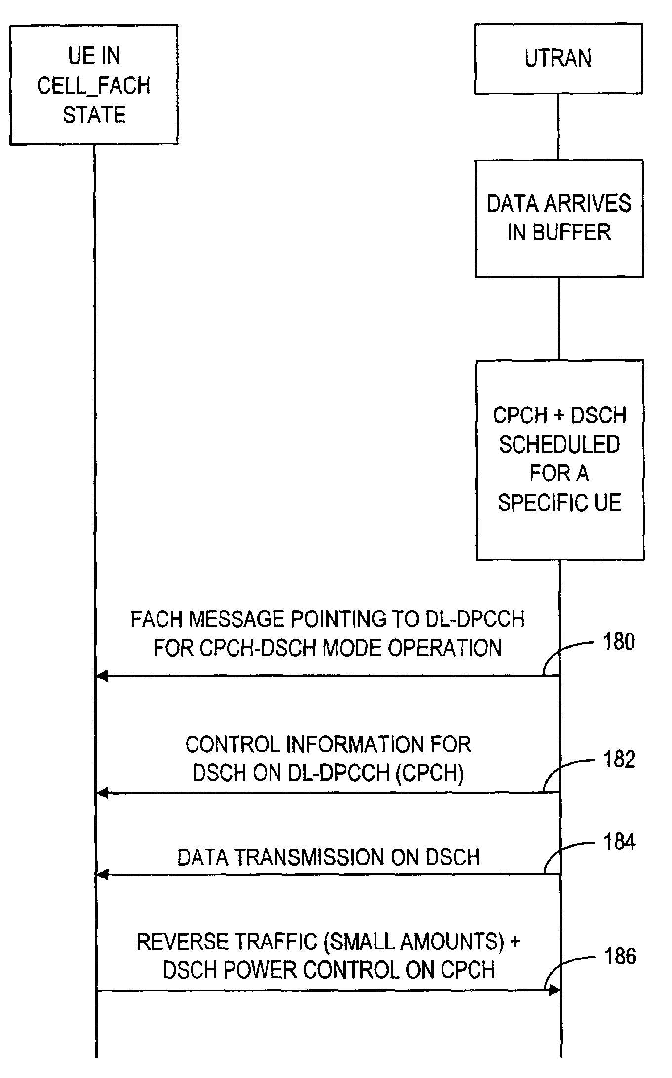
[0015]The above-mentioned object can be achieved by jointly using CPCH and DSCH to eliminate the frequent switching between the cell_FACH and the cell_DCH states that would otherwise happen for bursty traffic. In the pointer method above, this switching will not happen and the UE (and corresponding network entity) will remain in the cell_DCH state. The method, according to the present invention, allows the UE to remain in the cell_FACH state for both the packet active period and for the inactive “reading” period.
[0018]providing a message in a forward access channel (FACH) to the selected mobile mobile indicative of an operation mode using a further transportation channel different from the aDCH for carrying the physical control information between the selected mobile terminal and the communicating base station for avoiding the state-switching during the downlink packet switching.
[0025]means for providing a message in a forward access channel (FACH) to the selected mobile mobile indicative of an operation mode using a common packet channel (CPCH) for carrying the physical control information between the selected mobile terminal and the communicating base station for avoiding the state-switching during the downlink packet switching.
[0029]means for providing a message in a forward access channel (FACH) to the selected mobile mobile indicative of an operation mode using a specified common packet channel (CPCH) for carrying the physical control information between the selected mobile terminal and a communicating base station for avoiding the state-switching during the downlink packet switching.

Problems solved by technology

For web-type traffic and TCP sessions, packet generation is typically very bursty with short, high peak bitrate active periods and long in-activity periods.
For traffic like this, the dedicated transport channel resources are not used effectively.
The penalty of doing this is the delay caused by DCH setup signaling and synchronization.
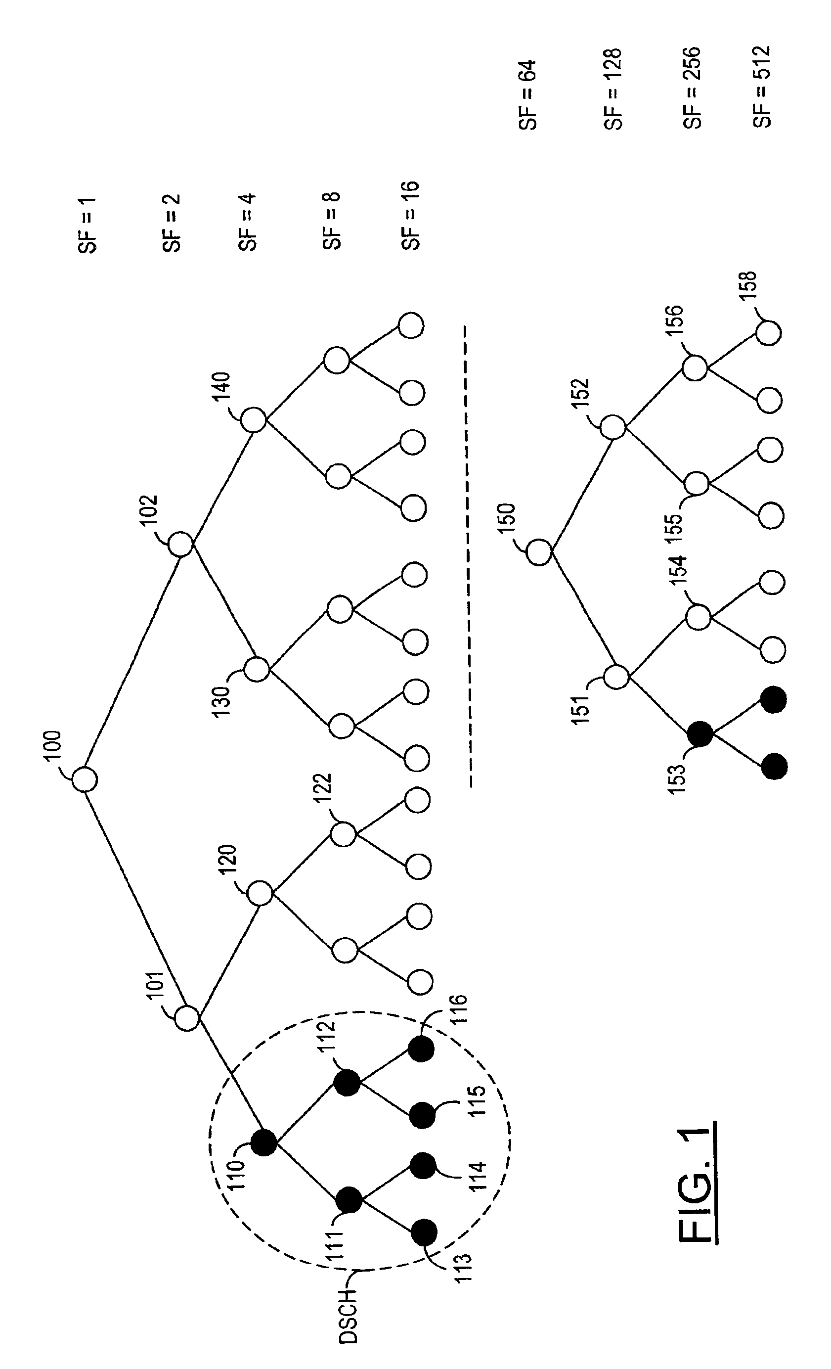
The settings for the associated DCH may be too demanding for some traffic sources from the cell code-tree resource point of view.
Similar problems exist also when trying to allocate any DCH for a high-bitrate bearer.
If the release timer for it is long, it unnecessarily consumes code-tree space, and if the spreading factor is low, it badly blocks other bearers.
Again, this causes the DCH setup delay.
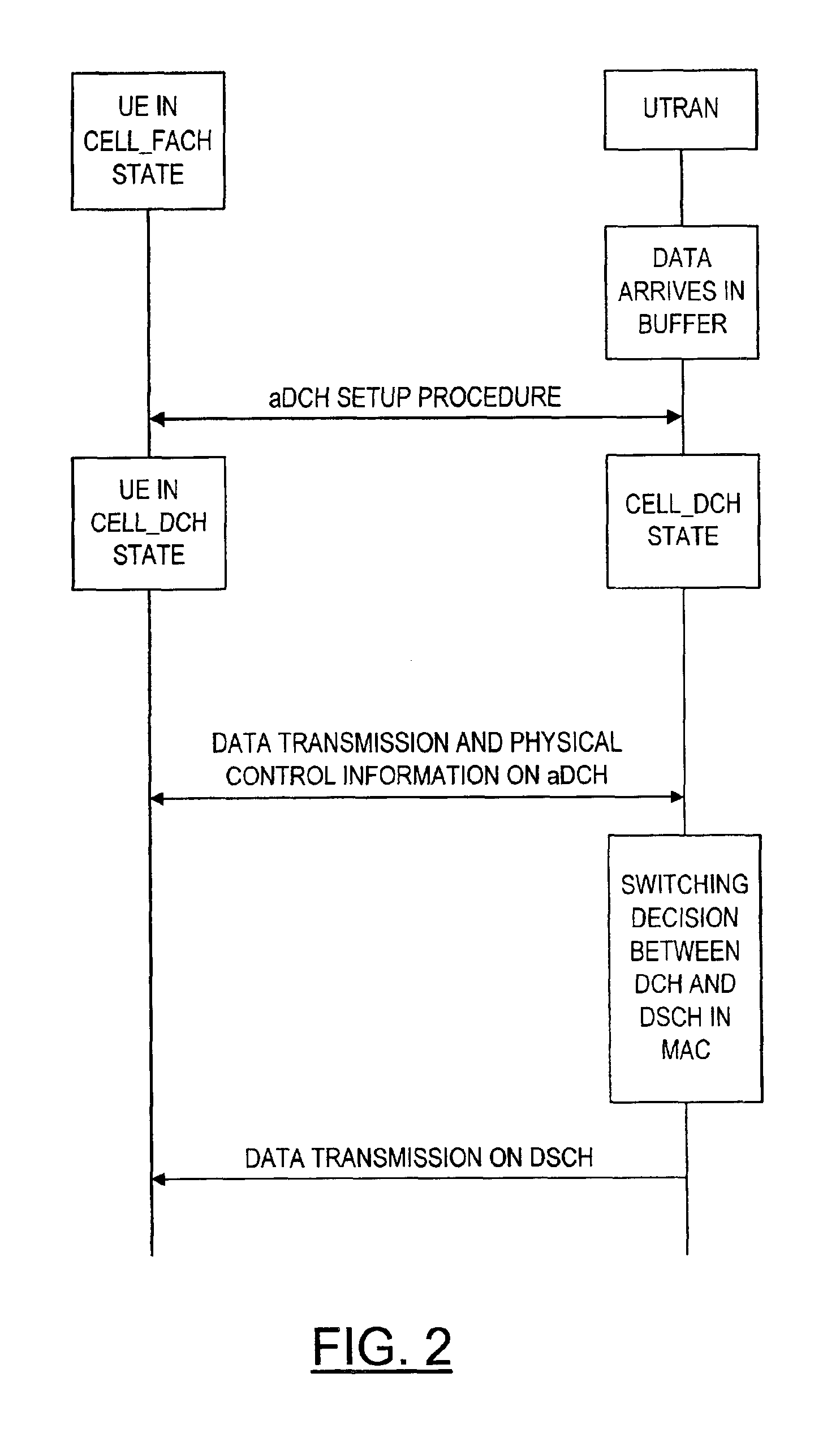
In a bursty traffic load, switching between the cell_FACH and cell_DCH states is very frequent, thereby causing a delay in packet data transmission.
The pointer method is feasible but still has the delays including setting up the aDCH.
One disadvantage is that in this solution the UE has to be capable of receiving, reading and decoding a large number of code channels at the same time.

Method used


Image

  • Method and device for downlink packet switching
  • Method and device for downlink packet switching
  • Method and device for downlink packet switching

Examples


Embodiment Construction

[0043]The present invention allows DSCH transmission without setting up the aDCHs by jointly using the CPCH and DSCH. This invention, still, does not make allocating aDCH obsolete for those UEs that have capabilites for that and which set-up bearers for traffic sources that benefit on alternate switching between DCH and DSCH transport. This invention provides means of using packet transport and fast switching even without the aDCH set-up. This invention may be advantageous for certain UE capability classes and for certain traffic bearer types. Actually, these two means can be used at the same time by different terminals communicating in the same cell using the DSCH; some terminals would use an aDCH+DSCH combination, other terminals would use a CPCH+DSCH combination. Thus, the CPCH is a counterpart of the DSCH. Diagrammatically, the transport channels involved in the connection procedure for downlink packet switching, according to the present invention, is shown in FIG. 4. As shown i...


PUM


Abstract

A method of downlink packet switching for use in a mobile telecommunications network having a plurality of base stations capable of communicating in corresponding uplink and downlink with a plurality of mobile terminals operating in a frequency division duplex (FDD) mode, wherein a downlink shared channel (DSCH) is used to carry user data and control information for the mobile terminals in a coverage area, the method comprising the steps of providing a common packet channel (CPCH) to serve as a reverse link transport of the downlink shared channel (DSCH) in a deterministic way; and providing for carrying a downlink dedicated physical control channel (DL-DPCCH) to provide physical transport format (TFCI) for the downlink shared channel and physical control for the uplink CPCH.

Description

FIELD OF THE INVENTION[0001]The present invention generally relates to a mobile telephone network and, more specifically, to a frequency division multiplex (FDD) mode of a mobile terminal of the mobile telephone network to provide communication links between the mobile terminal and one or more base stations.BACKGROUND OF THE INVENTION[0002]Universal Terrestrial Radio Access Network (UTRAN) is a conceptual term identifying a part of a radio communication network, wherein a plurality of mobile terminals communicate with each other or with a terminal in a PSTN or in a packet network (e.g. Internet) through one or more base stations. In particular, UTRAN identifies part of the network, which consists of radio network controllers (RNCs) and Node Bs between interconnection (Iu) and the radio interface (Uu). The interconnection Iu is an interface between an RNC and a core network, and the radio interface Uu is between UTRAN and the user equipment. This forms the basic architecture for the ...

Claims


Application Information

Patent Timeline
IPC IPC(8): H04L12/56
CPCH04W72/1273H04W72/1278H04W72/20H04L1/00
Inventor MATE, AMITRINNE, MIKA
Owner RPX CORP
Learn More