Footwear sole with a stiffness adjustment mechanism
a technology of stiffness adjustment and sole, applied in the field of footwear sole, can solve the problems of increasing the thickness of the midsole, the source of foot and leg injury, and the tendency to overpronation, so as to facilitate the movement of the band and alter the deflection and stiffness characteristics
- Summary
- Abstract
- Description
- Claims
- Application Information
AI Technical Summary
Benefits of technology
Problems solved by technology
Method used
Image
Examples
first embodiment
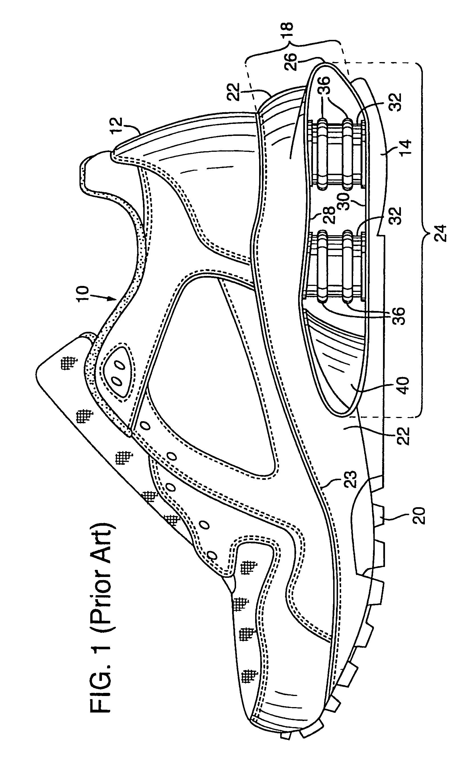
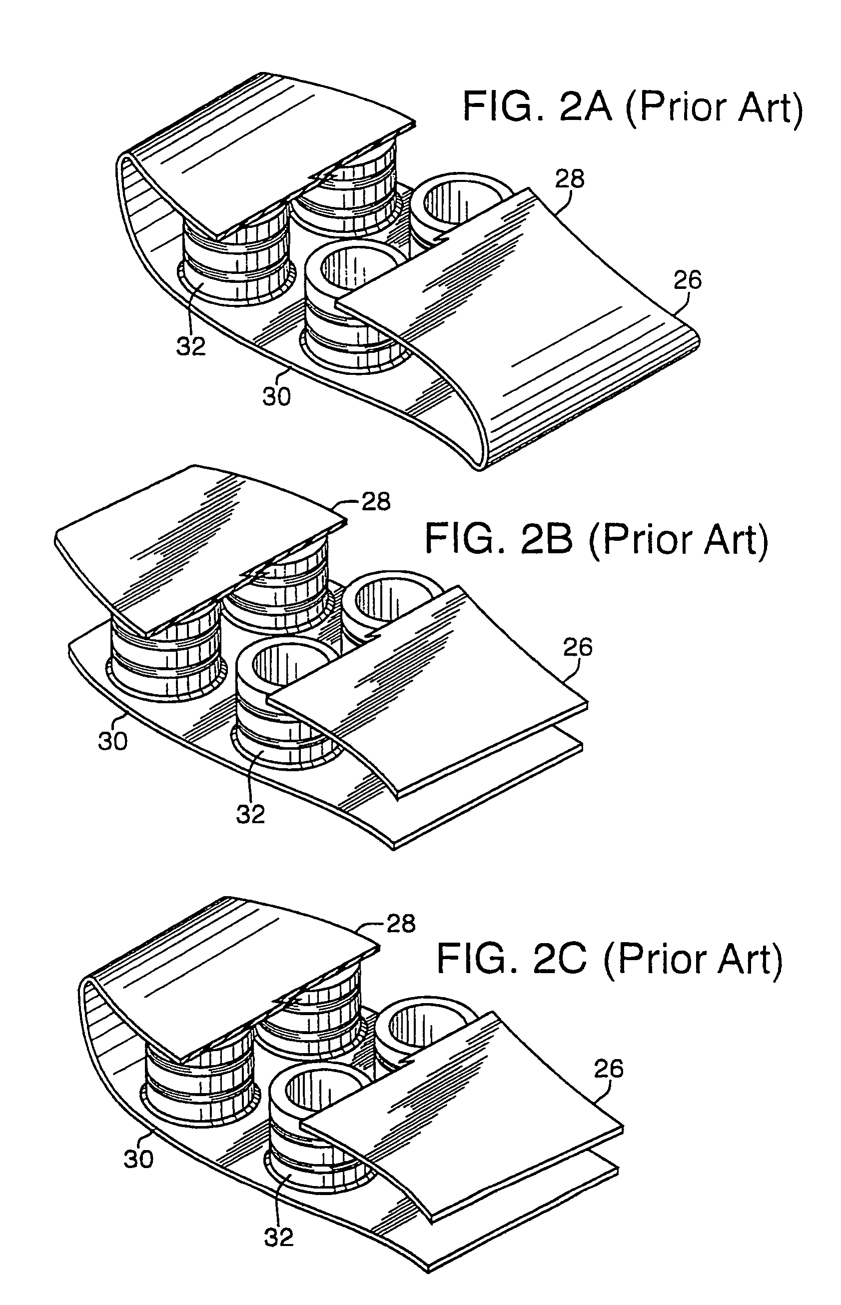
[0055]The present invention is applicable to a wide variety of footwear having support elements disposed in the sole. Depending upon the primary use for the footwear, the support elements may include either a flat or canted upper surface. For general information relating to footwear having support elements with a flat upper surface, see U.S. Pat. Nos. 5,353,523 and 5,343,639 to Kilgore et al., incorporated by reference. For general information relating to footwear having a canted upper surface see the detailed discussion concerning the first embodiment, included herein.
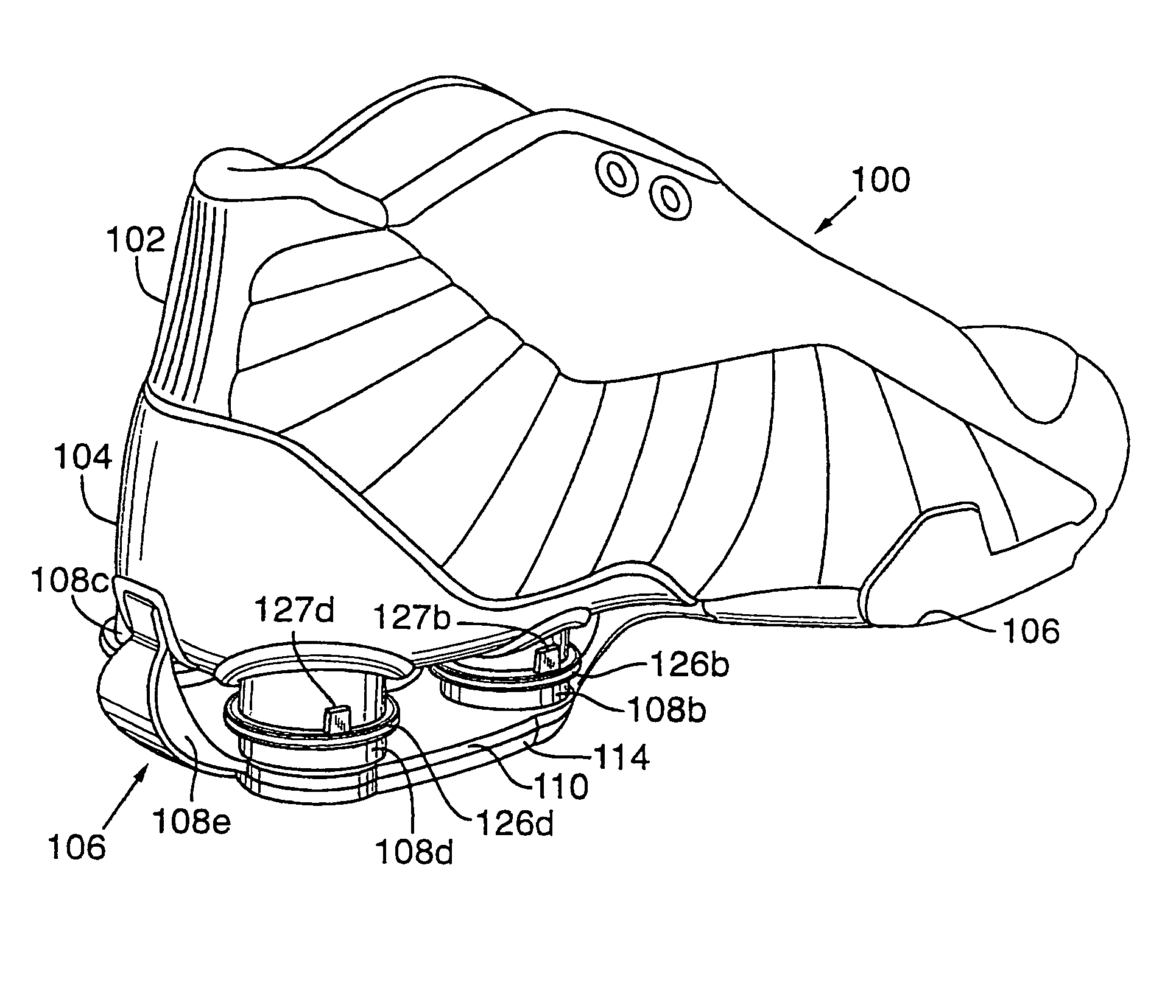
[0056]Support elements in accordance with a first embodiment of the present invention are disclosed in FIGS. 3–19. Shoe 100 includes three primary components: upper 102, heel plate 104, and sole 106. Sole 106 is further comprised of support elements 108, including columns 108a–108d and aft support 108e, base 110, base plate 112 (not visible), and outsole 114. Upper 102 is attached to heel plate 104 in the aft portion ...
second embodiment
[0078]Support elements in accordance with the present invention are illustrated in FIGS. 20–25. Each support element 200 includes exterior surface 210, top surface 212, bottom surface 214 and interior void 220. Inscribed longitudinally in exterior surface 210 are one or more access indentations 230, and encircling exterior surface 210 are one or more bands 250. Exterior surface 210 may slope outward from both the top and bottom of support element 200 such that the widest point forms a ridge in the middle of support element 200, thereby ensuring that the point of maximum deflection corresponds with the middle of support element 200. Support elements 200 may have a canted upper surface, as described in reference to columns 108. Accordingly, top surface 212 may be located substantially in the horizontal plane, as in FIG. 20, or may be canted, as in FIG. 21.
[0079]Exterior surface 210 may also include a structure that removably secures band 250 in one or more positions. As discussed belo...
PUM
| Property | Measurement | Unit |
|---|---|---|
| flexural modulus | aaaaa | aaaaa |
| flexural modulus | aaaaa | aaaaa |
| thickness | aaaaa | aaaaa |
Abstract
Description
Claims
Application Information
 - R&D
- Intellectual Property
- Life Sciences
- Materials
- Tech Scout
- Unparalleled Data Quality
- Higher Quality Content
- 60% Fewer Hallucinations
Browse by: Latest US Patents, China's latest patents, Technical Efficacy Thesaurus, Application Domain, Technology Topic, Popular Technical Reports.
© 2025 PatSnap. All rights reserved.Legal|Privacy policy|Modern Slavery Act Transparency Statement|Sitemap|About US| Contact US: help@patsnap.com


