
Multi-band spectral audio encoding

a multi-band spectral audio and encoding technology, applied in the field of multi-band spectral audio encoding, can solve the problems of reducing the dynamic range of the signal, affecting the quality of the signal,

Inactive Publication Date: 2005-11-22
NIELSEN COMPANY US LLC THE A DELAWARE LIMITED LIABILITY
View PDF123 Cites 210 Cited by
  • Summary
  • Abstract
  • Description
  • Claims
  • Application Information

AI Technical Summary

Benefits of technology

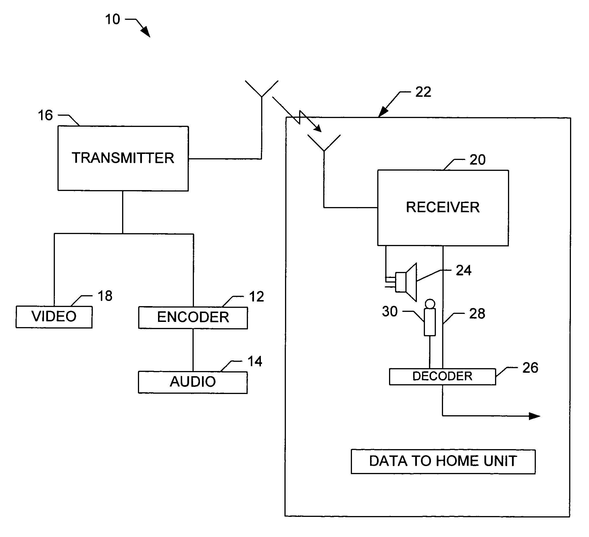
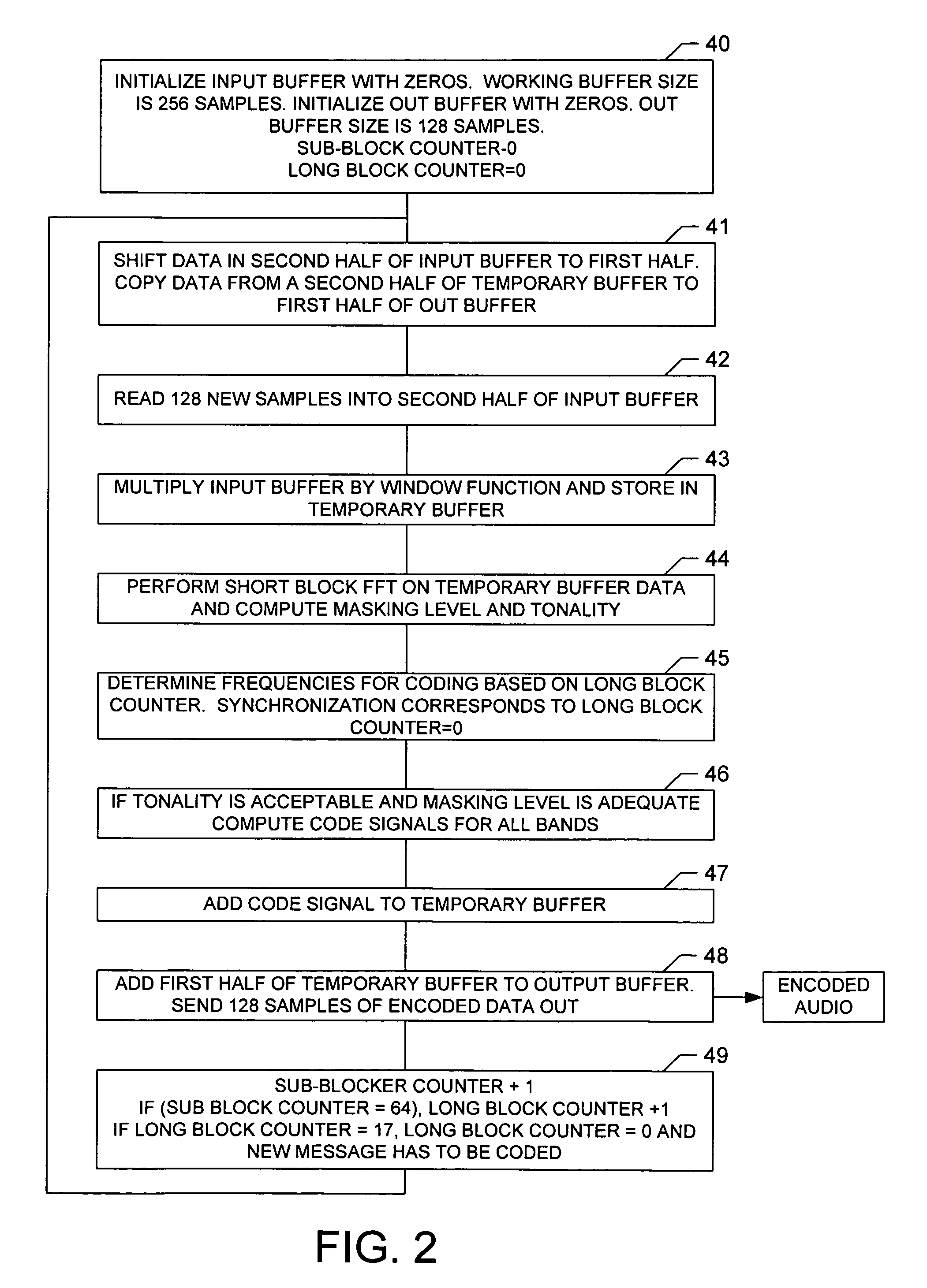
[0025]According to still aspect of the present invention, a method of encoding an audio signal comprises the following steps: a) generating a plurality of short blocks from the audio signal, wherein each of the short blocks has a duration less than a minimum audibly perceivable signal delay; b) combining the plurality of short blocks into a long block; c) transforming the long block into a spectrum comprising a plurality of independently modulatable frequency indices; and, d) modulating at least two of the indices so as to make one of the indices an extremum while keeping the total energy of a neighborhood of the modulated indices substantially constant.

Problems solved by technology

It will be recognized that, because ancillary codes are preferably inserted at low intensities in order to prevent the codes from distracting a listener of program audio, such codes may be vulnerable to various signal processing operations as well as to interference from extraneous electromagnetic sources.
For example, although Lee et al. discuss digitized audio signals, many of the earlier known approaches to encoding a broadcast audio signal are not compatible with current and proposed digital audio standards, particularly those employing signal compression methods that may reduce the signal's dynamic range (and thereby delete a low level code) or that otherwise may damage an ancillary code.
Left uncorrected, this delay results in a perceptible loss of synchronization between the audio and video portions of a viewed program.
These systems are thus vulnerable to interference, such as reverberation or multi-path distortion, that affect one of the encoded frequencies substantially more than the other.

Method used


Image

  • Multi-band spectral audio encoding
  • Multi-band spectral audio encoding
  • Multi-band spectral audio encoding

Examples


Embodiment Construction

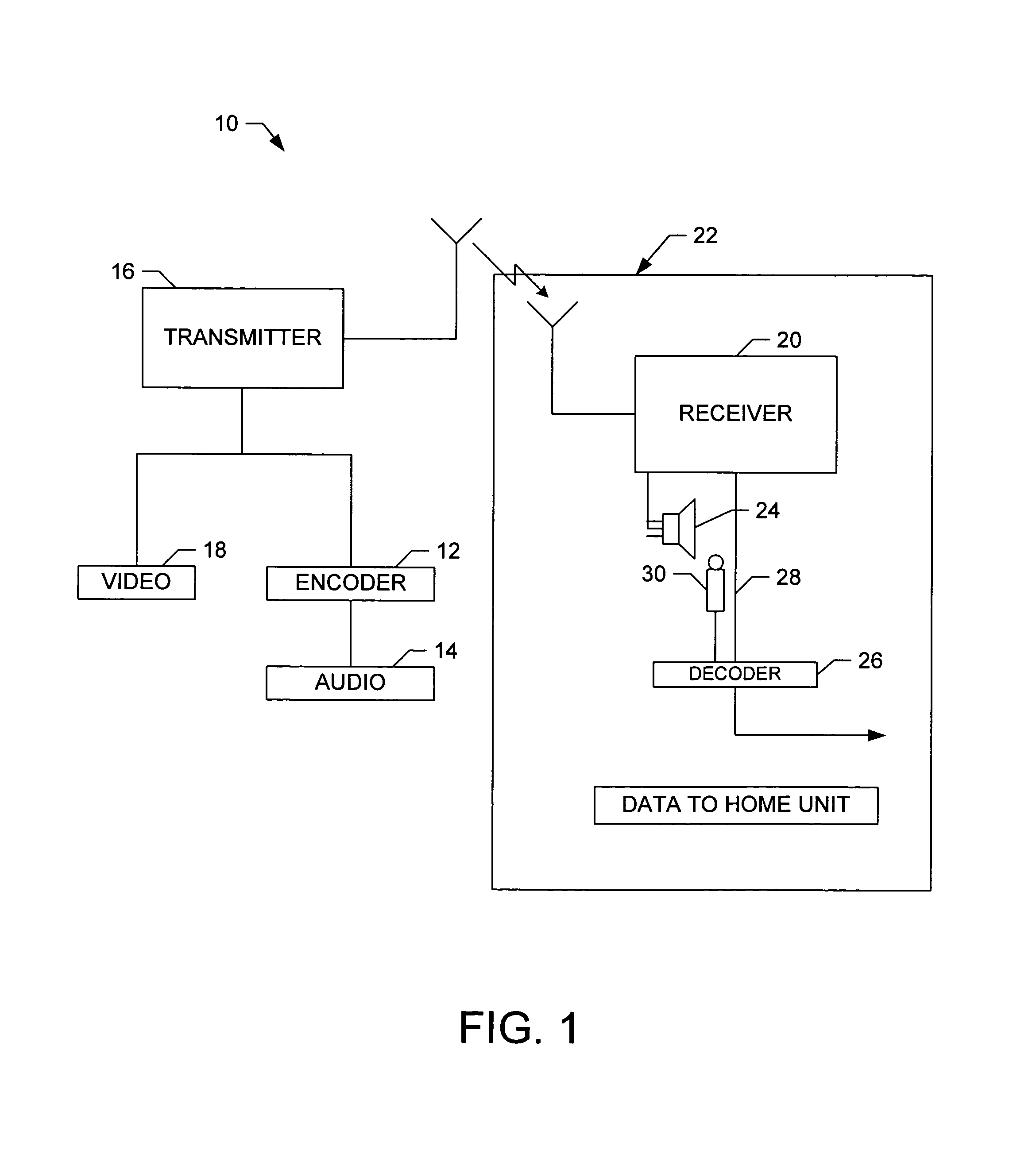
[0031]Audio signals are usually digitized at sampling rates that range between thirty-two kHz and forty-eight kHz. For example, a sampling rate of 44.1 kHz is commonly used during the digital recording of music. However, digital television (“DTV”) is likely to use a forty eight kHz sampling rate. Besides the sampling rate, another parameter of interest in digitizing an audio signal is the number of binary bits used to represent the audio signal at each of the instants when it is sampled. This number of binary bits can vary, for example, between sixteen and twenty four bits per sample. The amplitude dynamic range resulting from using sixteen bits per sample of the audio signal is ninety-six dB. This decibel measure is the ratio of the square of the highest audio amplitude (216=65536) to the square of the lowest audio amplitude (12=1). The dynamic range resulting from using twenty-four bits per sample is 144 dB. Raw audio, which is sampled at the 44.1 kHz rate and which is converted t...


PUM


Abstract

An encoder includes a sampler that samples an audio signal and that generates from the samples a plurality of short blocks of sampled audio. Each of the short blocks has a duration less than a minimum audibly perceivable signal delay. A processor combines the plurality of short blocks into a long block. The long block is transformed into a frequency domain signal having a plurality of independently modulatable frequency indices. The frequency difference between adjacent indices is determined by the minimum duration and the sampling rate of the sampler. A neighborhood of frequency indices is selected so that the frequency difference between a lowest index and a highest index within the neighborhood is less than a predetermined value. Two or more of the indices are modulated in the neighborhood so as to make a selected one of the indices an extremum while keeping the total energy of the neighborhood constant. A plurality of frequency bands are so coded. A decoder decides that a bit or bits have been received if, in a majority of the frequency bands, the decoder detects a modulated index.

Description

RELATED APPLICATION[0001]This application contains disclosure similar to the disclosure in U.S. patent application Ser. No. 09 / 116,397 filed Jul. 16, 1998, in U.S. patent application Ser. No. 09 / 427,970 filed Oct. 27, 1999, and in U.S. patent application Ser. No. 09 / 428,425 filed Oct. 27, 1999.TECHNICAL FIELD OF THE INVENTION[0002]The present invention relates to a system and method for adding an inaudible code to an audio signal and for subsequently retrieving that code. Such a code may be used, for example, in an audience measurement application in order to identify a broadcast program.BACKGROUND OF THE INVENTION[0003]There are many arrangements for adding an ancillary code to a signal in such a way that the added code is not noticed. For example, it is well known in television broadcasting that ancillary codes can be hidden in non-viewable portions of video by inserting the codes into either the video's vertical blanking interval or the video's horizontal retrace interval. An exe...

Claims


Application Information

Patent Timeline
Patent Type & Authority Patents(United States)
IPC IPC(8): H04H1/00G10L19/02G10L19/018G10L25/51H03M7/30H04H20/31
CPCH04H20/31
Inventor SRINIVASAN, VENUGOPAL
Owner NIELSEN COMPANY US LLC THE A DELAWARE LIMITED LIABILITY
Learn More