
Image reading apparatus and method

Inactive Publication Date: 2005-11-22
FUJIFILM CORP +1
View PDF5 Cites 7 Cited by
  • Summary
  • Abstract
  • Description
  • Claims
  • Application Information

AI Technical Summary

Benefits of technology

[0010]In order to overcome the above problems, an object of the present invention is to provide an image reading apparatus and method in which no complicated control is carried out and suitable adjustment of the color balance can be carried out in accordance with the type of photographic material.

Problems solved by technology

Therefore, a problem exists in that, if a film image is read without correcting the difference in the transmittance characteristics, the color balance of the film image is lost and a variable range of the charge accumulation time of a CCD is used up, and as a result, color correction cannot be effected.
In this case, since the signal-to-noise (S / N) ratio is low, a rough image is formed, or a dull image is formed due to color mixing.
Therefore, there is a drawback in that control for varying the offset densities and adjustment of the respective portions is complicated.

Method used


Image

  • Image reading apparatus and method
  • Image reading apparatus and method
  • Image reading apparatus and method

Examples


first embodiment

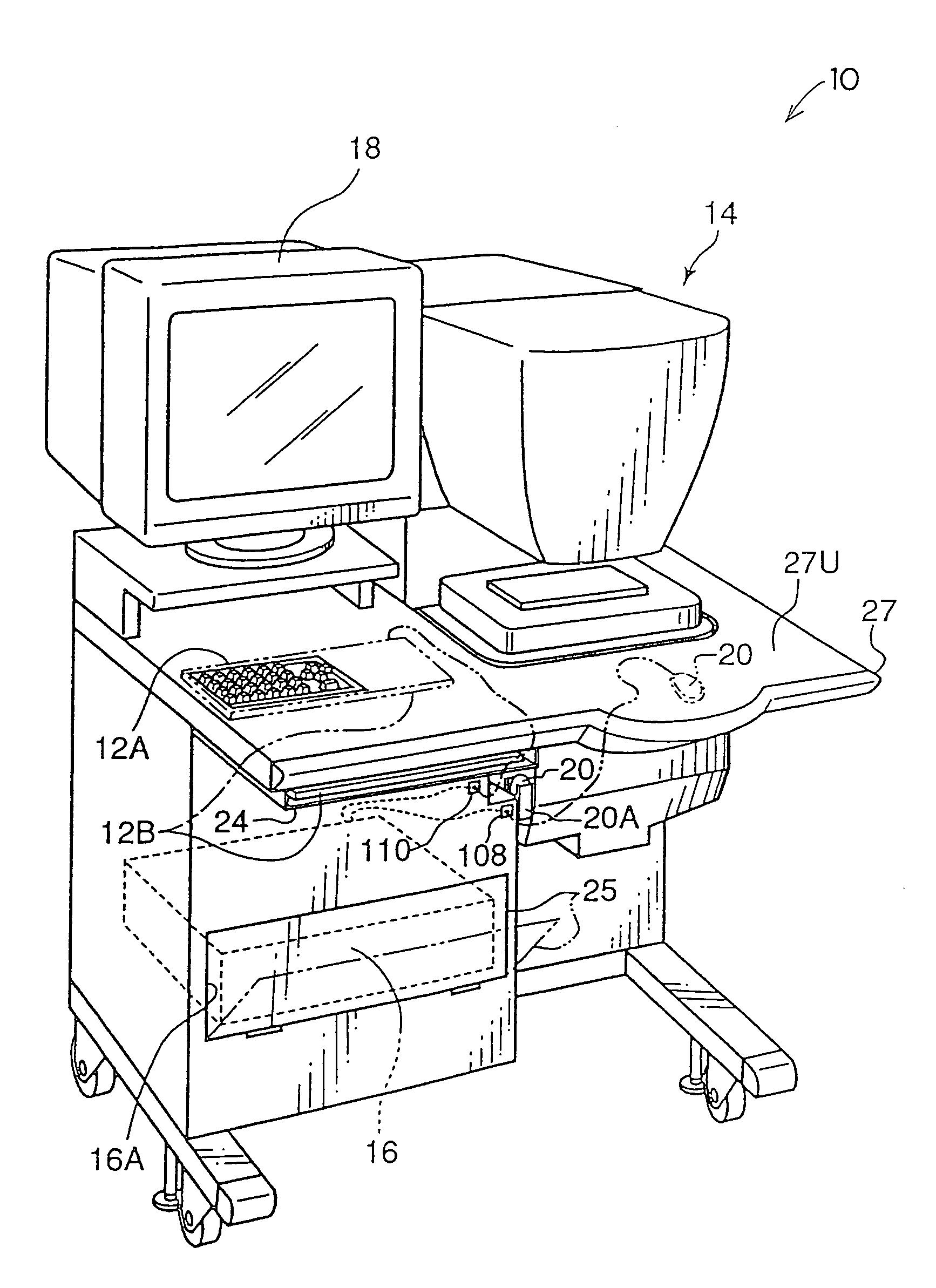
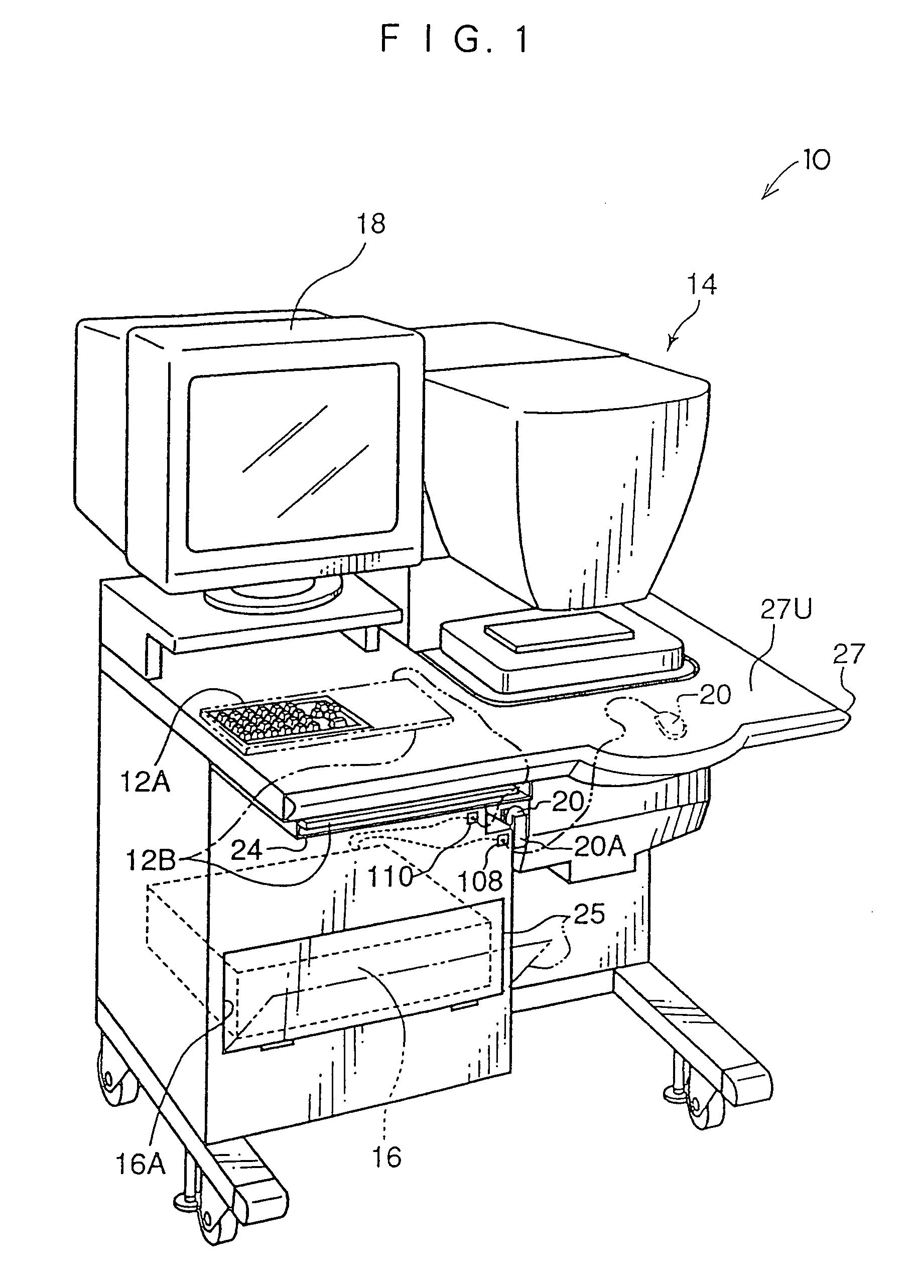
[0070]As shown in FIG. 1, an image reading apparatus 10 in accordance with a first embodiment of the present invention includes a linear CCD scanner 14. The linear CCD scanner 14 is provided at a work table 27, which is equipped with an image processing section 16, a mouse 20, two types of keyboards 12A and 12B, and a display 18.

[0071]One of the keyboards, the keyboard 12A, is embedded in a work surface 27U of the work table 27. When not in use, the other keyboard, the keyboard 12B, is accommodated in a drawer 24 of the work table 27, and when in use, the keyboard 12B is taken out of the drawer 24 and is laid on the keyboard 12A. At this time, the cord of the keyboard 12B is connected to a jack 110 which is connected to the image processing section 16.

[0072]The cord of the mouse 20 is connected through a hole 108, which is provided at the work table 27, to the image processing section 16. When not in use, the mouse 20 is accommodated within a mouse holder 20A, and when in use, the m...

second embodiment

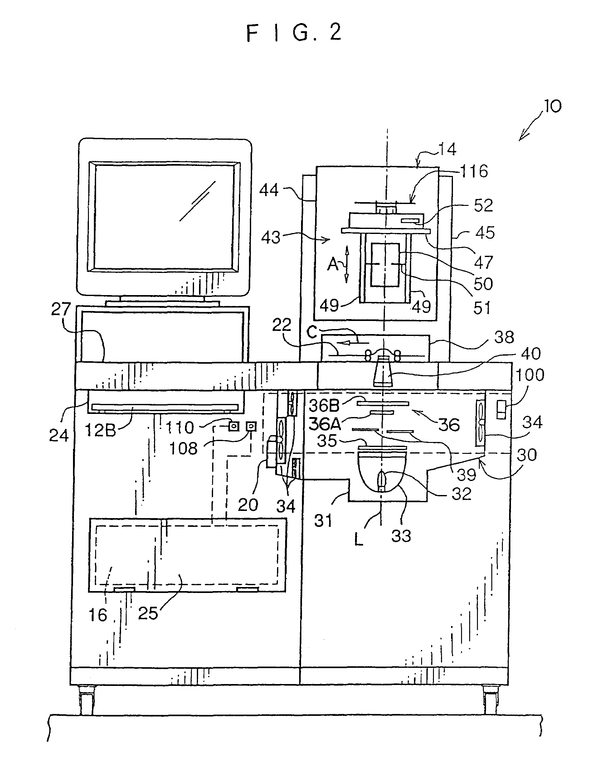
[0150]In the first embodiment, a case has been described in which the filter section 36 serving as the optical filter device of the present invention is disposed between the lamp 32 and the photographic film 22. In a second embodiment, a case will be described in which the filter section is disposed between the photographic film 22 and the linear CCD 116 and near the linear CCD 116.

[0151]First, the structure of an image reading apparatus 10′ according to the present second embodiment will be described with reference to FIGS. 9 and 10. Components in the present second embodiment which are similar to those of the image reading apparatus 10 according to the first embodiment will be designated by the same reference numerals as those in FIGS. 3 and 4, and detailed description thereof will be omitted.

[0152]As shown in FIGS. 9 and 10, the image reading apparatus 10′ according to the present second embodiment is different from the image reading apparatus 10 according to the first embodiment...


PUM


Abstract

An image reading apparatus and method in which no complicated control is carried out and suitable adjustment of the color balance can be carried out in accordance with the type of a photographic material. First, the type of a photographic film to be read is acquired. When the photographic film is a negative film or a sepia-tone film, a filter for negative film is set on an optical axis of illumination light. When the photographic film is a positive film or a black-and-white film, a filter for positive film is set on the optical axis of illumination light. In either state, a film image on the photographic film is read.

Description

BACKGROUND OF THE INVENTION[0001]1. Field of the Invention[0002]The present invention relates to an image reading apparatus and method, and more particularly to an image reading apparatus and method in which a developed photographic material is illuminated and an image recorded on the photographic material is read on the basis of light transmitted therethrough.[0003]2. Description of the Related Art[0004]In recent years, photographic processing methods have been proposed in which a film image recorded on a photographic material such as a developed photographic film (hereinafter referred to simply as a photographic film) is read in such a manner as to be separated into component colors of R, G and B, and image data obtained by reading the film image is subjected to image processings such as various corrections, and thereafter, an image is recorded on a recording material or is shown on a display.[0005]Generally, in an image reading apparatus which is used to read film images in this ...

Claims


Application Information

Patent Timeline
IPC IPC(8): G03F3/08G03F3/00H04N3/02H04N1/46H04N5/253H04N1/407H04N1/56H04N1/60
CPCH04N1/407H04N1/6094
Inventor KATAKURA, KAZUHIKO
Owner FUJIFILM CORP
Learn More