
Multi-layer filter structure and use of a multi-layer filter structure

Inactive Publication Date: 2005-11-22
BRANOFILTER +1
View PDF22 Cites 56 Cited by
  • Summary
  • Abstract
  • Description
  • Claims
  • Application Information

AI Technical Summary

Benefits of technology

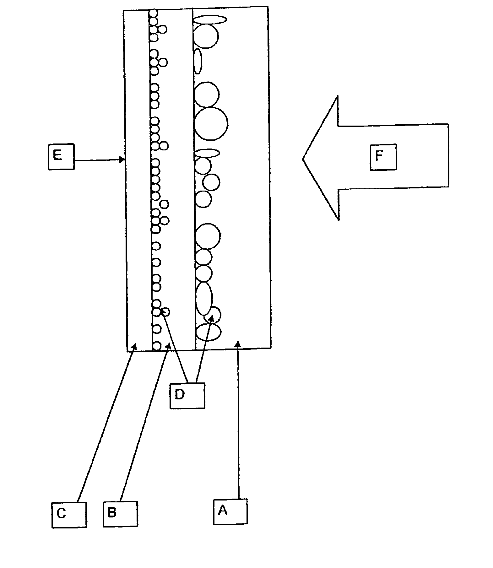
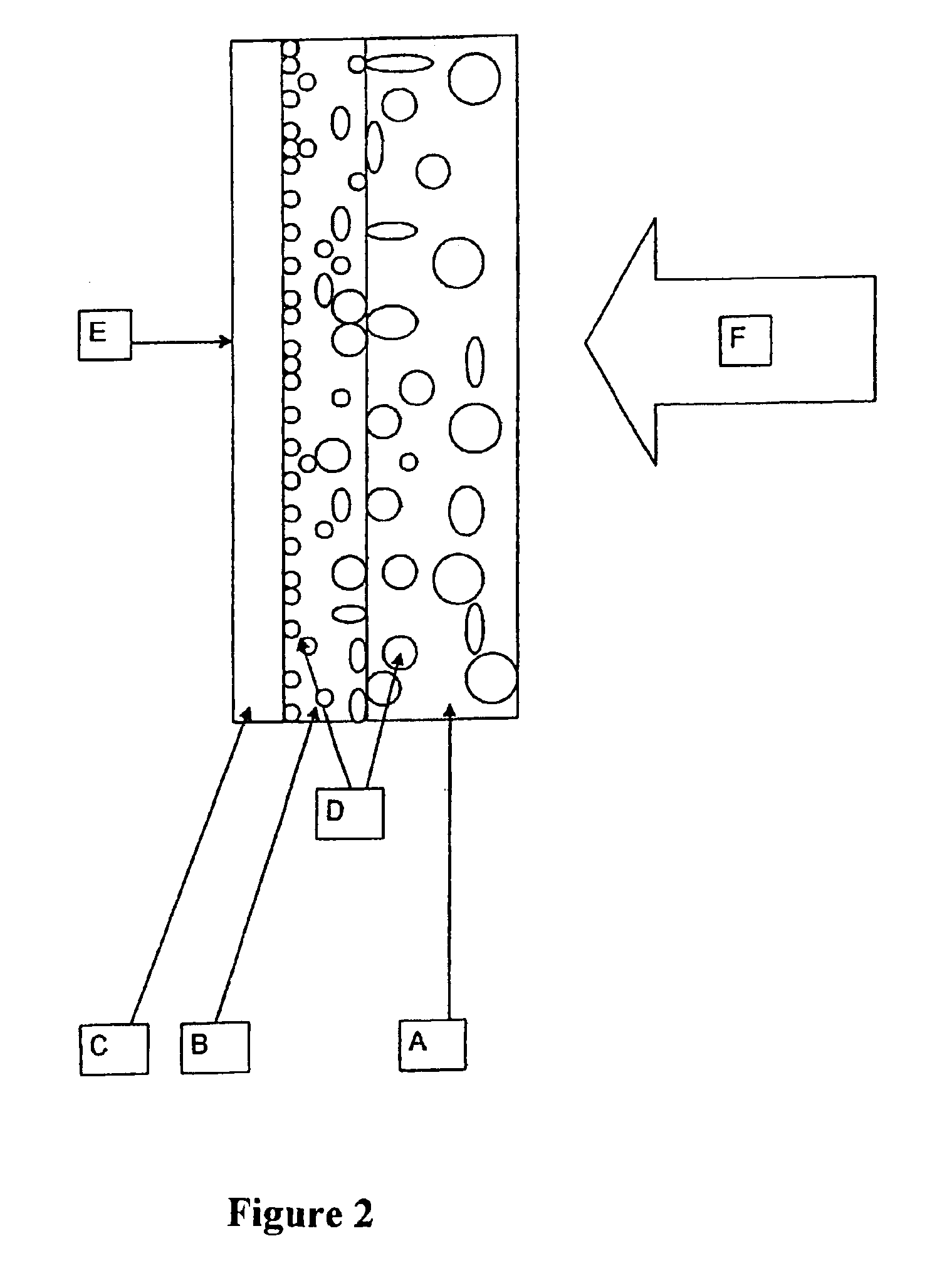
[0010]This distribution of the dust collection that is characteristic for filter media produced according to the prior art, of the type used for vacuum cleaner bags according to the preamble causes a significant increase in the differential pressure, particularly at the beginning and towards the end of their time in use. This results in a reduced cleaning power of the vacuum cleaner and, hence, also in a reduced dust collection efficiency.
[0014]The pores in a nonwoven exist as hollow spaces between the fibers, i.e., the smaller the selected fiber diameter and / or the higher the selected compaction of the nonwoven, the smaller the resulting pore size. To prevent an abrupt transition due to different pore sizes in the region of the contacting surfaces of the filter layers it is necessary that the contacting filter regions have approximately the same fiber diameter.

Problems solved by technology

However, due to the relatively thin filter paper layer, nanofiber layer, and meltblown layer that are used, the collection capacity of the material is low as dust particles can collect only in the surface region of the filter.
This results in a reduced cleaning power of the vacuum cleaner and, hence, also in a reduced dust collection efficiency.

Method used


Image

  • Multi-layer filter structure and use of a multi-layer filter structure
  • Multi-layer filter structure and use of a multi-layer filter structure
  • Multi-layer filter structure and use of a multi-layer filter structure

Examples


Embodiment Construction

[0022]FIG. 2 shows the characteristic distribution of the dust particles (D) within the coarse dust filter layer (A) and fine dust filter layer (B) on the inventive multi-layer filter structure (E) in the cross section.

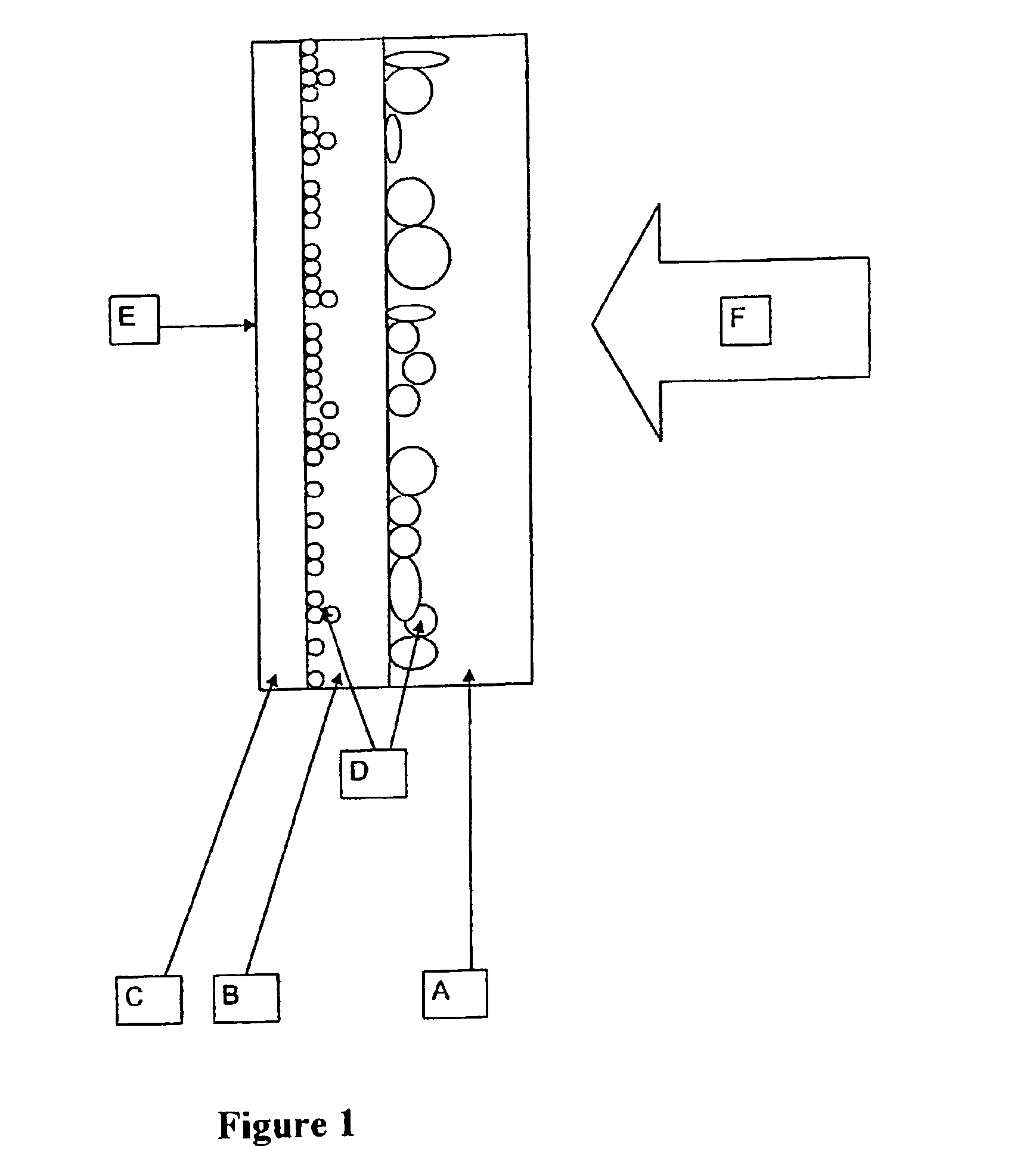
[0023]In FIG. 3 the inventive progressive filter structure (E) of the coarse dust filter layer (A) and fine dust filter layer (B) is shown in the cross section.

[0024]For the inventive multi-layer filter structure (E) a filter medium is used as the coarse dust filter layer (A), which consists, for example, of a carded nonwoven that is needled on one side and thermally hardened, and which is composed of randomly oriented curled staple fibers comprising a first synthetic staple fiber with a first fiber fineness and at least one second synthetic staple fiber with a second fiber fineness.

[0025]The desired gradient is attained in such a way that the arrangement of differently fine staple fibers is selected so that the more coarse staple fibers (G) lie on the side facing the...


PUM

PropertyMeasurementUnit
Weightaaaaaaaaaa
Weightaaaaaaaaaa
Weightaaaaaaaaaa

Abstract

The invention describes a multi-layer filter structure and the use of a multi-layer filter structure for the dust removal from gases, wherein a coarse dust filter layer, a fine dust filter layer, and a support layer are disposed behind one another in the direction from the inflow side to the outflow side, and which is designed such that the fiber diameter distribution within the coarse dust filter layer and fine dust filter layer has a gradient, and that the fiber diameters of the coarse dust filter layer and fine dust filter layer continually decrease from the inflow side to the outflow side.This multi-layer filter structure may be used in a filter cassette for industrial dust removal, as well as in a stationary or mobile home dust cleaning device.

Description

BACKGROUND OF THE INVENTION[0001]1. Prior Art[0002]To increase the efficiency of filter media, for example filter units in stationary or mobile dust removal systems or also in ventilation and air conditioning systems, numerous efforts have been made in the past.[0003]In DE 19919809 A1, a dust filter bag for use in vacuum cleaners is described, which consists of at least one nonwoven layer and at least one support material layer and which is suitable for the efficient removal of fine dust particles without significantly reducing the cleaning power of the vacuum cleaner. However, due to the relatively thin filter paper layer, nanofiber layer, and meltblown layer that are used, the collection capacity of the material is low as dust particles can collect only in the surface region of the filter.[0004]A multi-layer vacuum cleaner filter bag with a very good dust removal action is also revealed in EP 0960645 A2. The layer structures with their varied designs generally contain one wet-laid...

Claims


Application Information

Patent Timeline
IPC IPC(8): A47L9/10B01D39/16B01D46/52B01D46/00B01D46/10B01D46/02B01D46/12B32B5/18A47L9/12A47L9/14
CPCA47L9/12A47L9/14B01D39/163B01D46/0028B01D46/02B01D46/12B01D2239/0414B01D2239/0442B01D2239/0636B01D2239/0659B01D2239/0668B01D2275/10B01D2275/305Y10S55/02Y10S55/39
Inventor RAMMIG, JURGENSCHMIERER, UWEHORNFECK, ULRICHSTRAUB, ROLAND
Owner BRANOFILTER
Learn More