
Firefighter locator

a firefighter and locator technology, applied in direction finders, breathing protection, instruments, etc., can solve the problems of unsuitable gps system, loss of signal strength, inability to locate moving objects, etc., to eliminate or eliminate ambiguities, and reduce the number of ambiguities

Inactive Publication Date: 2005-11-15
INFORMATION SYST LAB
View PDF12 Cites 30 Cited by
  • Summary
  • Abstract
  • Description
  • Claims
  • Application Information

AI Technical Summary

Benefits of technology

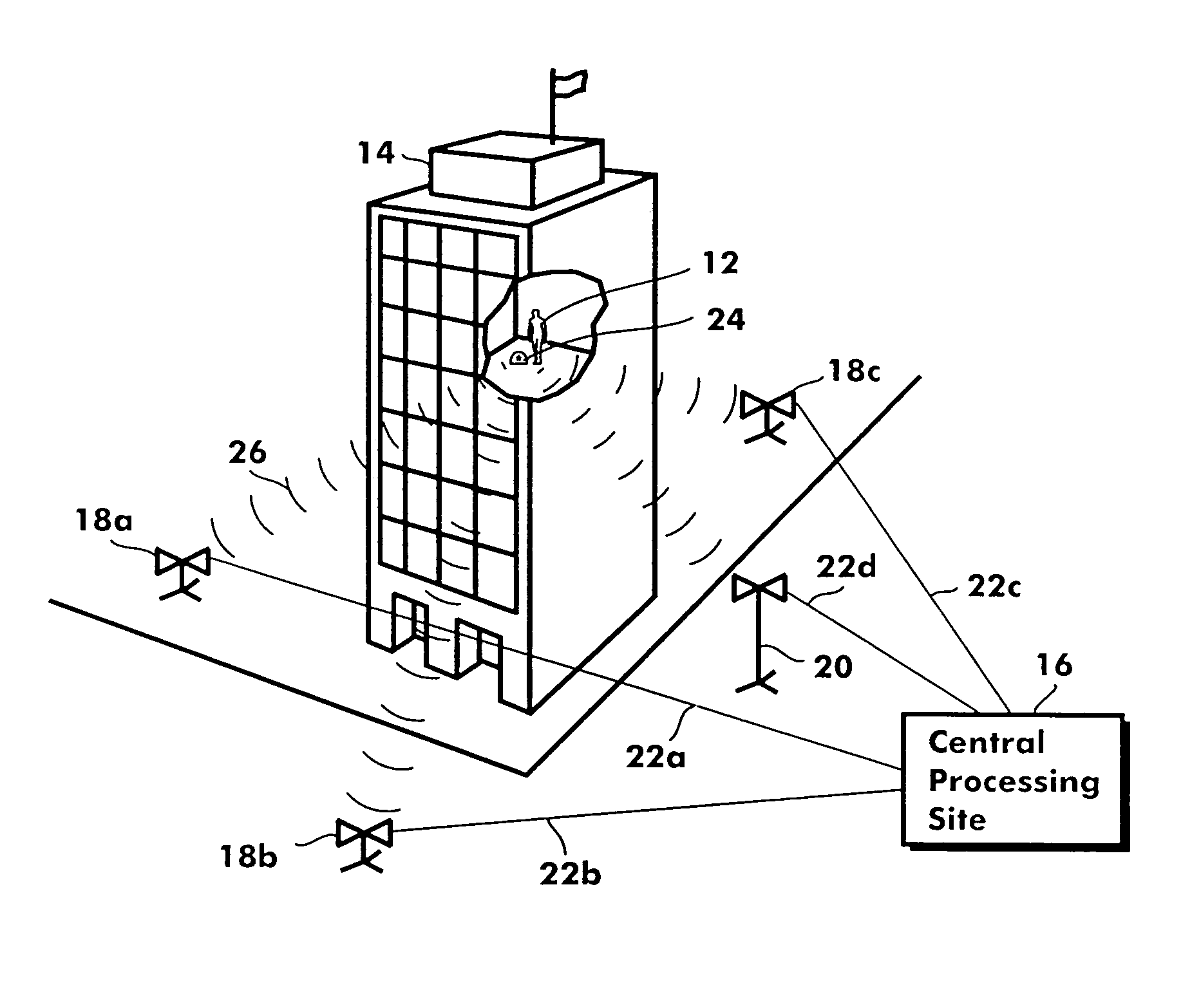
[0013]Next, the ambiguities can be eliminated by the processor to find the real emitter position. It is to be appreciated that the number of ambiguities will depend on the emitter signal wavelength and the coverage area. Several techniques can be used to reduce or eliminate the ambiguities. For example, increasing the number of base stations will generally reduce the number of ambiguities. Another technique involves determining an initial position for the emitter and tracking the movement of the emitter. This technique allows for some of the ambiguous positions to be eliminated as improbable in light of any known limitations on emitter movement such as speed. Another technique involves using an algorithm known in the pertinent art such as the maximum likelihood method (MLM). Another technique for eliminating ambiguities involves using an emitter that transmits multiple frequencies. Here, each frequency produces a set of possible emitter positions. The set of possible positions produced at one frequency can be compared to the set of possible positions produced at a second frequency and any positions that are not common to both sets can be eliminated as ambiguities. Once the ambiguities have been eliminated, the remaining point is the real position of the signal emitter relative to the base station sites.
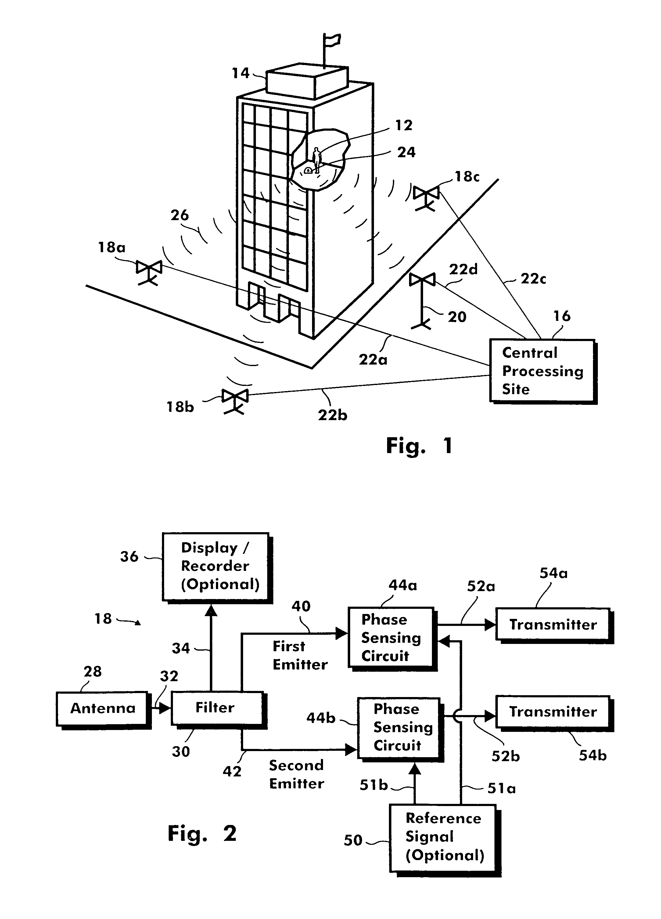
[0014]In another embodiment of the present invention, rather than actual phase delays, relative phase delays from one base station to another can be used to locate the position of a signal emitter. In this embodiment, the location of each base station is known and each base station is synchronized with the other base stations. Synchronization between the emitter and the base stations is not necessary. Each base station measures the phase angle of the emitter signal and records a measurement time. These data are transferred to the central processing site where the processor calculates a set of relative phase delays. Alternatively, the base stations can relay the received signals to the central processing site where the phase angles and measurement times can be determined and used to calculate a set of relative phase delays. For this purpose, the received signal can be time shifted or frequency shifted at the base station and the shifted signal relayed to the central base site thereby reducing signal interference.

Problems solved by technology

This is particularly so when the individual or object is moving in a hostile or dangerous environment.
Although an object's position can be determined effectively outdoors using the current global positioning system (GPS), the GPS system is unsuitable, without augmentation, for locating moving objects indoors at accuracies of approximately one meter.
Lack of adequate signal penetration can result in a loss of signal strength which in turn can cause unacceptable location errors.
Unfortunately, radiofrequency (RF) systems using high frequency signals are limited in their ability to penetrate the walls and features of a structure.
However, in time-of-arrival systems, increased resolution can only be obtained at the expense of increased bandwidth.
Unfortunately, this much bandwidth (tens of MHz) is unavailable at the low frequencies required for indoor use.
Consequently, for the low frequency RF signals required for indoor locating, each antenna would be quite large and costly.
Further, such large antennas would be unsuitable for a firefighter locator system which requires small, portable equipment that can be setup quickly.

Method used


Image

  • Firefighter locator
  • Firefighter locator
  • Firefighter locator

Examples


Embodiment Construction

[0009]In accordance with the present invention, a system and method for locating and tracking the position of a movable signal emitter that is situated inside a structure includes establishing at least three mutually dispersed base station sites outside the structure at known locations. For a multistory structure, the system preferably includes three base station sites located at approximately ground level, and an additional base station site that is elevated. A central processing site is also included in the system, and a wireless link is provided to allow for communication from each of the base station sites to the central processing site.

[0010]To operate the system, the emitter is turned on to transmit a continuous low frequency (approximately 27 Mhz) RF signal. An omni-directional antenna mounted on the emitter allows for the transmission of the signal in all directions. Each base station site has an antenna for receiving the continuous signal. Preferably, each base station site...


PUM


Abstract

A wireless system and method for locating the position of a movable signal emitter located inside or adjacent to a structure includes establishing at least three base station sites at known locations around the structure. The signal emitter then transmits an omni-directional, low frequency, RF signal that is received at the base station sites. Phase information is measured at each base station site and communicated to a central processing site. At the central processing site, relative phase delays are used to geometrically calculate the position of the signal emitter.

Description

FIELD OF THE INVENTION[0001]The present invention pertains generally to a system for locating and tracking moving objects. More particularly, the present invention pertains to systems and methods that are useful for locating the position of a person inside a structure. The present invention is particularly, but not exclusively, useful as a portable, accurate system capable of being rapidly setup to track and locate the position of firefighters inside a burning structure.BACKGROUND OF THE INVENTION[0002]There are many circumstances wherein there is a need to establish the accurate positioning and tracking of movable objects or individuals. This is particularly so when the individual or object is moving in a hostile or dangerous environment. One example is when a firefighter enters a structure during a rescue operation. In situations such as this, there is a need to determine the position of the firefighter from outside the structure with accuracies of approximately one meter. Althoug...

Claims


Application Information

Patent Timeline
IPC IPC(8): G08B21/00G08B21/02A62B99/00
CPCG08B21/02
Inventor HALSEY, J. DOSSWOLFF, DOUGLAS J.
Owner INFORMATION SYST LAB
Learn More