Electro-optical transducer with multi-reflector beam-expanding and collimating input/output device

Inactive Publication Date: 2005-11-08
SANMINA-SCI CORPORATION
View PDF41 Cites 14 Cited by
  • Summary
  • Abstract
  • Description
  • Claims
  • Application Information

AI Technical Summary

Benefits of technology

[0016]In accordance with the present invention, the foregoing objects are met by the provision of an electro-optical transducer with an input / output optical transmission system in which the output is spread by a double-reflector optical system which avoids the problems of using refracting devices for such purposes.
[0021]Preferably, in both the transducer device and fiber-optic cable terminus, the system of reflectors is like that in a Cassegrainian or Ritchey-Chretien reflecting telescope system. Such systems have been used for many years in the field of astronomy. Applicants have recognized that, even though the telescope systems usually are very large and expensive, the small devices used in this invention can be made relatively inexpensively. The use of reflectors or mirrors rather than lenses tends to minimize the effects of refraction which so often increases the difficulty in the optical design process for the usual prior art proposals for beam-expanding connectors.
[0022]The resulting optical system is very compact, relatively amenable to standardization and inexpensive to manufacture.
[0023]In accordance with another feature of the present invention, the problem of aligning transducers or light conductors in fiber-optic cables is substantially alleviated by coupling a magnetically permeable element to the object to be aligned, applying a magnetic field to the magnetically permeable member, and controlling the field to move and align the objects with one another. Movement in at least two orthogonal axes is preferred.
[0026]It also is preferred that the magnetic field source be one for developing a rotating magnetic field which rotates around the object to be aligned, with an electrical network being provided to control the field. This allows movement of the effective center of the magnetic field, and precise positioning of the object being aligned.
[0028]The invention also provides a compact integrated optical device for spreading and collimating light. A block of transparent material such as glass or plastic, is provided with surfaces shaped to form reflectors of the size, shape and position desired, and then those surfaces are coated with a reflecting material such as metal. This can be done at a reasonable cost by vapor deposition, sputtering, etc. Other surfaces of the block are given an anti-reflective coating.

Problems solved by technology

The provision of optical transmission systems in the use of electro-optical transducers long has presented problems, particularly in communications systems using fiber-optic cable for transmission.
Coupling to electro-optical transducers has been complicated by the very small diameter of light beams transmitted as well as the small size of semiconductor devices often used to generate or detect the signals.
Any foreign objects, such as dirt and dust, which accumulate in the optical path of the signals can seriously compromise the integrity and operability of the system.
Difficult problems specific to the use of fiber-optic cable for transmission also are well known.
For example, providing suitable end termini and connectors for connecting two fiber-optic cables together long has been a demanding problem.
Aligning the cables accurately usually is a time-consuming and exacting process.
Standard commercial butt-joint type single-mode fiber-optic connectors suffer from numerous problems.
First, they are relatively delicate, sensitive to dirt, difficult to clean, and easily damaged.
The problems are even greater with multi-channel connectors which must function in a hostile environment.
However, prior expanded beam connectors and techniques suffer from several problems.
Such problems include relatively high optical losses and high cost.
In fact, the cost has been considered to be prohibitive for many commercial applications.
Furthermore, it is believed that the prior designs are relatively difficult or even impossible to be installed correctly in the field; that is, outside of a factory, laboratory, or other such facility.

Method used


Image

  • Electro-optical transducer with multi-reflector beam-expanding and collimating input/output device
  • Electro-optical transducer with multi-reflector beam-expanding and collimating input/output device
  • Electro-optical transducer with multi-reflector beam-expanding and collimating input/output device

Examples


Embodiment Construction

Terminus

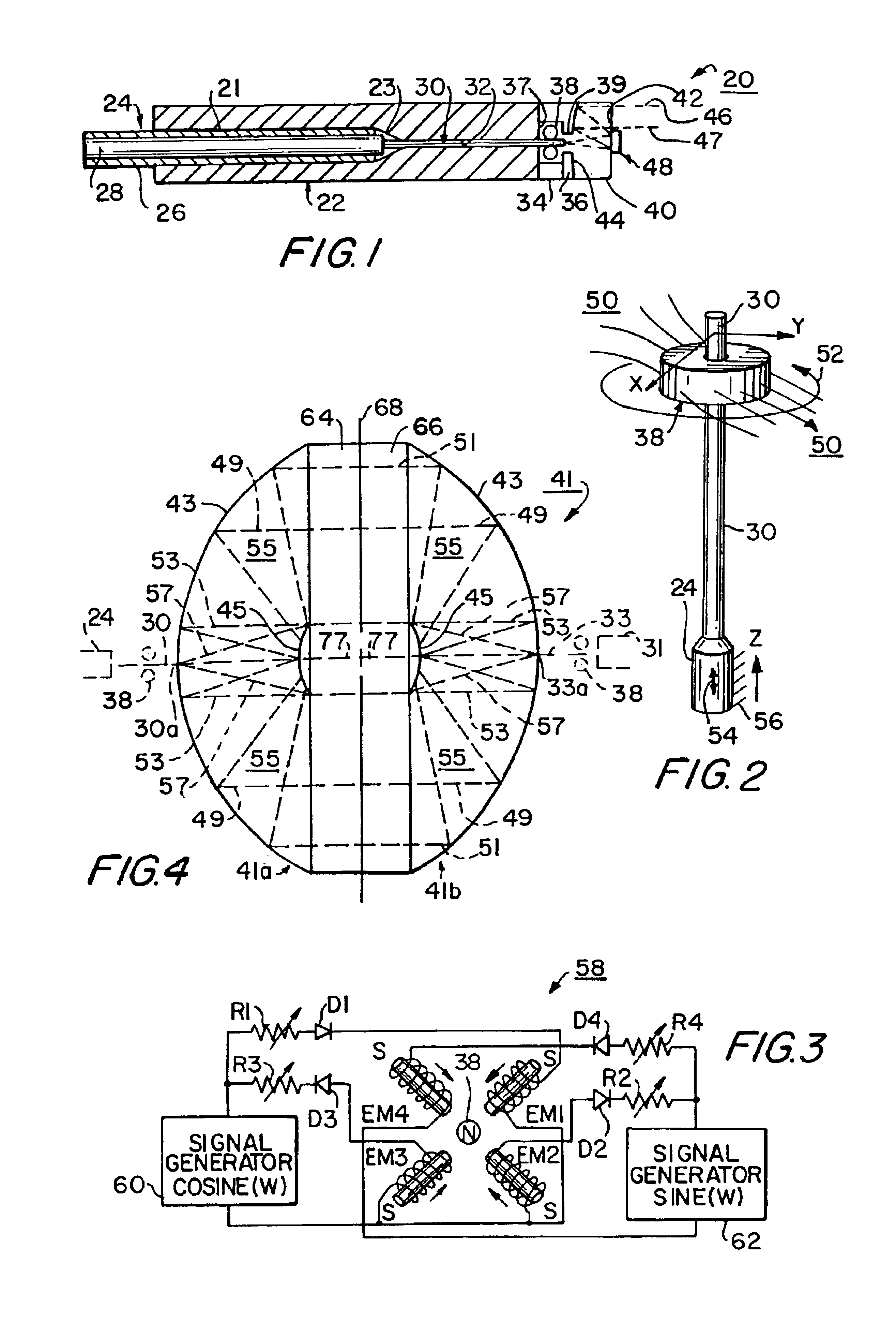
[0048]FIG. 1 is a cross-sectional view of a fiber-optic cable terminus 20 constructed in accordance with the present invention.

[0049]Terminus 20 includes a standard ceramic ferrule 22 with a relatively large bore 21 which tapers down at 23 to form a substantially smaller fiber conductor passageway 32.

[0050]Fitted into the ferrule is the end of a fiber-optic cable 24 including a light-conducting single-mode fiber 30 extending through the passageway 32, and cladding 28 having an index of refraction different from that of the light-conducting core 30, and, finally, an outer protective coating 26. Typical dimensions for the cable are: The outer diameter of the cable with the coating 26 is 250 micrometers; the diameter of the cable without the coating 26 is 125 micrometers; and the diameter of the light-conducting fiber or core 30 is 8 micrometers.

[0051]The dimensions of the cable are small; especially the diameter of the core, which has a diameter of only 0.008 millimeters (arou...


PUM


Abstract

A system of reflectors is used to form beam-expanding and collimating electro-optic transducer devices, including radiation sources and / or detectors. Preferably, the reflector system is of the Cassegrainian or Ritchey-Chretien type. Radiation such as light signals can be conducted to or from the transducers by fiber-optic cables. Alignment of optical conductors or “cores” of the fiber-optic cables or the reflector system with a transducer is provided by coupling a magnetic member to the conductor or reflector system and applying a controllable magnetic field from outside of the device to provide alignment, and then fixing the components in place by the use of means such as light-curable epoxy resin.

Description

[0001]This patent application is a continuation-in-part of U.S. patent application Ser. No. 09 / 909,100, filed Jul. 19, 2001 now U.S. Pat. No. 6,625,376. Priority also is claimed in this patent application from a provisional patent application entitled PROJECT CASTLE, Ser. No. 60 / 267,544, filed in the United States Patent and Trademark Office on Feb. 9, 2001.BACKGROUND OF THE INVENTION[0002]This invention relates to electro-optic transducers and optical transmission devices, and particularly to light-emitting and detecting transducers and light transmission systems therefor, and to devices and methods for aligning such systems and transducers. This invention also relates to fiber-optic cable, and particularly to termini, connectors, alignment devices and optical systems and methods for terminating and connecting fiber-optic cable.[0003]The provision of optical transmission systems in the use of electro-optical transducers long has presented problems, particularly in communications sy...

Claims


Application Information

Patent Timeline
IPC IPC(8): G02B6/42H04B10/04G02B6/38
CPCG02B6/3803G02B6/4207G02B6/4225G02B6/4234H04B10/50G02B6/4227
Inventor WERKHEISER, ARTHUR H.PORTER, DAVID R.JOHNSON, RALPH BARRY
Owner SANMINA-SCI CORPORATION
Why Eureka
Try Eureka