
Color wheel of segment type

a color wheel and segment technology, applied in the field of color wheels, can solve problems such as cost disadvantage, and achieve the effect of convenient alignment and fixation to the motor and sufficient bonding strength

Inactive Publication Date: 2005-11-08
MINEBEA CO LTD
View PDF27 Cites 14 Cited by
  • Summary
  • Abstract
  • Description
  • Claims
  • Application Information

AI Technical Summary

Benefits of technology

[0010]The present invention has been made in light of the circumstances described above, and it is an object of the present invention to inexpensively provide a high-precision color wheel of segment type.
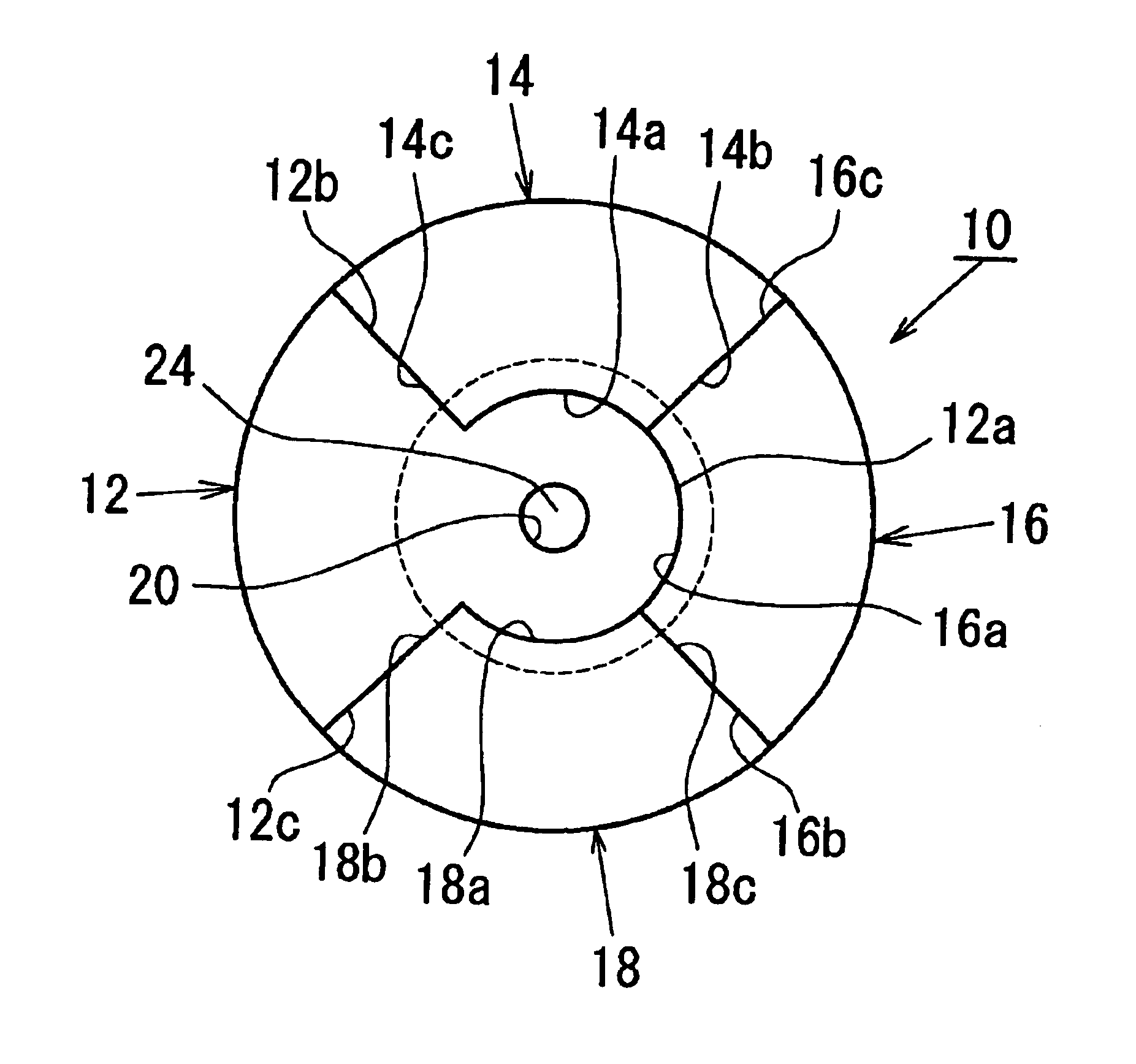
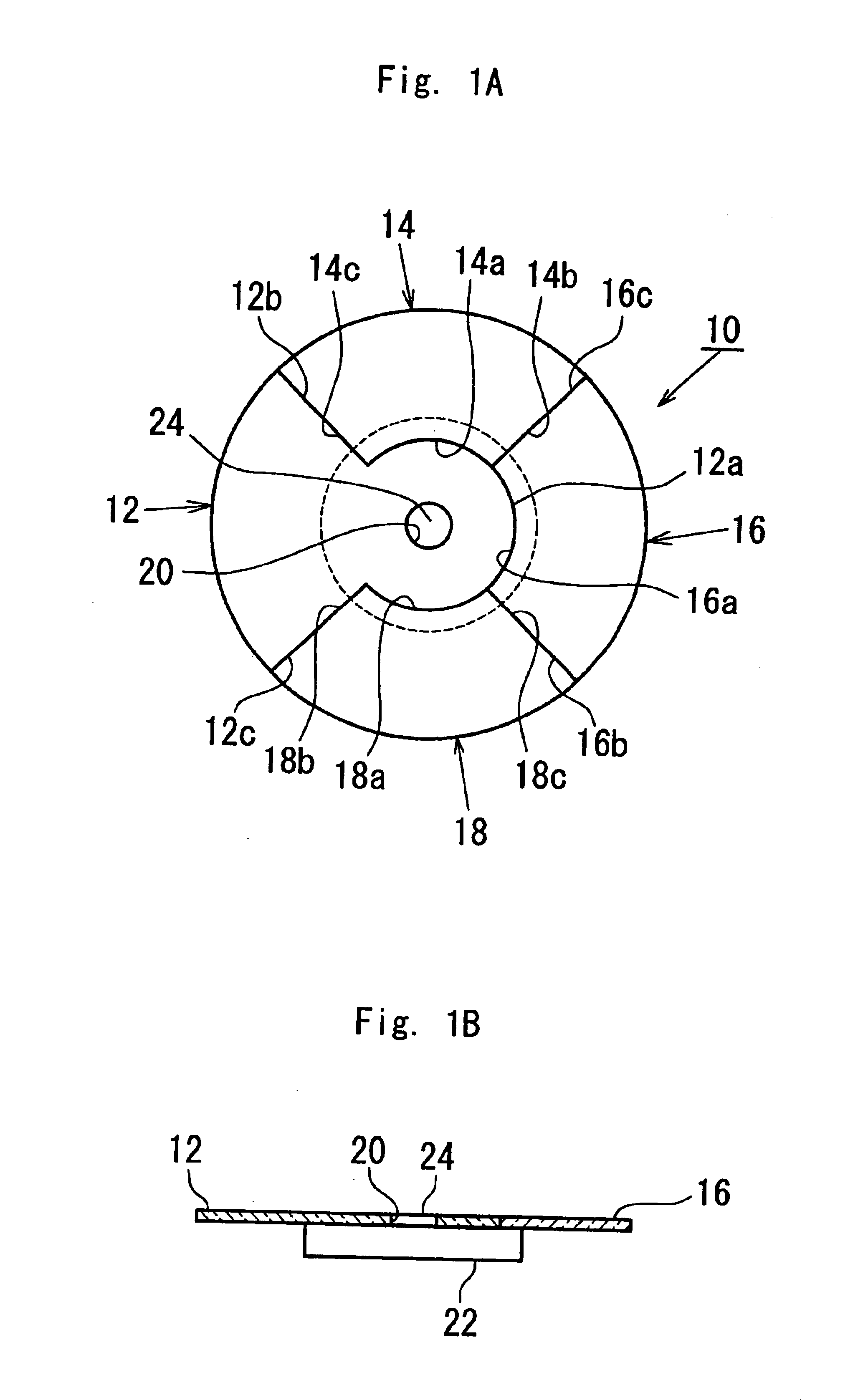
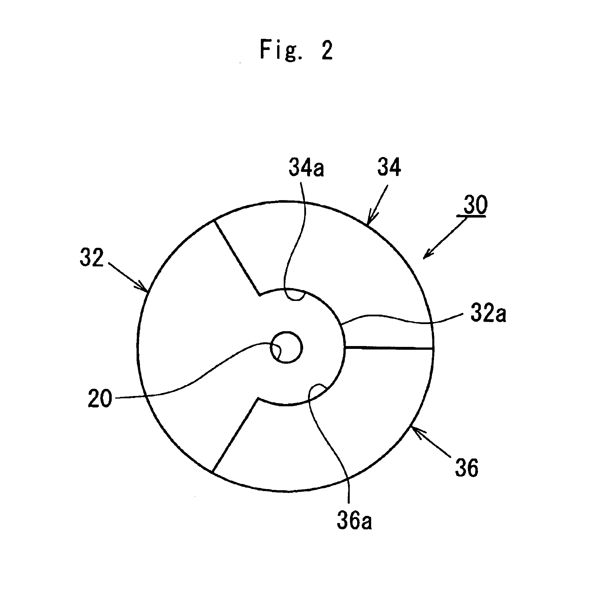
[0011]In order to achieve the object described above, according to one aspect of the present invention, a color wheel comprises a plurality of sectorial color filter segments disposed so as to form a disk, and at least one of the color filter segments has a core portion to which the inner circumferences of remaining color filter segments are directly fitted. The color wheel thus structured does not necessarily require a support member to which the color filter segments are fitted so as to be duly positioned in the color wheel assembled. Also, since the color wheel is composed of the color filter segments alone therefore requiring only machines to process the color filter segments, machine accuracy can be managed easily compared to when additional components, such as a support member, which must be precisely fitted together with the color filter segments, are employed thus requiring additional machines.
[0013]In the one aspect of the present invention, the core portion of the at least one color segment may constitute a central portion of the color wheel, and may have a hole concentric with the center axis of the color wheel. Consequently, the color wheel can be easily aligned and fixed to a motor.
[0014]In the one aspect of the present invention, the core portion of the at least one color filter segment may define an outer perimeter configured complementary to the inner circumferences of the remaining color filter segments. With this structure, the advantages described above can be better achieved. Further, if the configuration is arranged so as to increase the fitting area between the outer perimeter of the core portion of the at least one color filter segment and the inner circumferences of the remaining color filter segments so that sufficient bonding strength is attained therebetween, then the support member can be definitely eliminated, and the segment-type color wheel can be handled like a monolithic-type color wheel thus enjoying advantages available with a monolithic-type color wheel.
[0015]And, in the one aspect of the present invention, the outer perimeter of the core portion of the at least one color filter segment, and the inner circumferences of the remaining color filter segments may be configured with an undercut so that the remaining color filter segments are locked up in the radial direction. Thus, the color filter segments can be surely prevented from getting scattered off due to centrifugal force when the color wheel spins at high speed.

Problems solved by technology

A monolithic-type color wheel structured with a single substrate makes it easy to maintain the geometric accuracy and therefore easy to hold down the generation of vibrations and noises at the time of spinning, but requires sophisticated processes of forming color filters on the substrate thus resulting in cost disadvantage.

Method used


Image

  • Color wheel of segment type
  • Color wheel of segment type
  • Color wheel of segment type

Examples


first embodiment

[0024]Referring to FIG. 1A, a color wheel 10 according to the present invention comprises a plurality of sectorial color filter segments (hereinafter referred to simply as “segments” as appropriate) 12, 14, 16 and 18 which are fixedly set together so as to form a disk. The segment 12 consists of a sector portion, and a circular core portion which is integrally formed at the inner circumferential area of the sector portion, has a center hole 20, and defines an outer perimeter 12a. Respective inner circumferences 14a, 16a and 18a of the segments 14, 16 and 18, are directly fitted to the outer perimeter 12a of the circular core portion of the segment 12, and when the segments 12, 14, 16 and 18 are thus set together in place to complete the color wheel 10, the circular core portion of the segment 12 is located at the central area of the color wheel 10 such that the center hole 20 is concentric with the center axis of the color wheel 10.

[0025]The segments 14, 16 and 18 are duly positione...

second embodiment

[0033]Referring now to FIG. 3, a color wheel 40 according to the present invention comprises four (same as in FIG. 1A) segments 42, 44, 46 and 48. The segment 42 consists of a sector portion and a core portion formed integrally at the inner circumferential area of the sector portion. The core portion has a center hole 20, and defines an outer perimeter 42a to which respective inner circumferences 44a, 46a and 48a of the segments 44, 46 and 48 are directly fitted. The core portion of the segment 42 defines three recesses at the outer perimeter 42a so as to form humps 42d, and the segments 44, 46 and 48 define, at the inner circumferences 44a, 46a and 48a, respective protrusions which are configured complementary to the three recesses of the segment 42 for engaging attachment. The recesses of the segment 42, and the protrusions of the segments 44, 46 and 48 may be formed in any optional configurations complementary to each other, and alternatively protrusions may be formed at the oute...

third embodiment

[0035]Referring to FIG. 4, a color wheel 50 according to the present invention comprises four segments 52, 54, 56 and 58. The segment 52 consists of a sector portion, and an outer core portion formed integrally at the inner circumferential area of the sector portion. The outer core portion of the segment 52 is shaped substantially into a three-quarter ring with an open mouth positioned at an area opposite to the sector portion, defines an outer perimeter 52a separated by the open mouth into two portions to which respective inner circumferences 54a and 58 of the segments 54 and 58 adjacent to the segment 52 are directly fitted, and defines an inner perimeter 52e shaped like a U-letter. The segment 56 consists of a sector portion and an inner core portion formed integrally at the inner circumferential area of the sector portion. The inner core portion of the segment 56 is configured complementary to an opening defined by the inner perimeter 52e of the segment 52, has an center hole 20...


PUM


Abstract

In a color wheel comprising plurality of color filter segments, one of the filter segments consists of a sector portion, and a circular core portion which is formed intergrally at the inner circumferential area of the sector portion, and which is located at the center of the wheel assembled. The inner circumferences of the remaining filter segments are fitted directly to the outer perimeter of the circular core portion of the one segment, whereby the geometric accuracy of the color wheel can be achieved. Also, the alignment process of the filter segments for preventing the color wheel from generating vibrations and noises at the time of spinning at high speed can be simplified or even eliminated thus preventing the number of manufacturing processes from increasing.

Description

BACKGROUND OF THE INVENTION[0001]1. Field of the Invention[0002]The present invention relates to a color wheel suitable for use as a filter element of a time-share light dispersing device, and more specifically to a color wheel of segment type.[0003]2. Description of the Related Art[0004]Color composition in a projection-type image display apparatus has conventionally been accomplished commonly by a method, such as: a single-panel method, in which one light valve element adapted to control light amount per pixel thereby creating an image is used to disperse each pixel into R (red), G (green), and B (blue) lights; and a three-panel method, in which three light valve elements dedicated to R, G and B lights, respectively, are used to produce R, G and B images in parallel, and then the three images thus produced are composed. Recently, as a light valve element capable of fast switching, such as a ferroelectric liquid crystal display element or a digital micro-mirror device, is increasin...

Claims


Application Information

Patent Timeline
IPC IPC(8): G02B5/22G02B7/00
CPCG02B26/008G02B7/006
Inventor NIWA, SHINICHIASAKAWA, TOSHIAKIADACHI, SHIGEYUKITAKAO, KUNIYUKI
Owner MINEBEA CO LTD
Learn More