Eureka AIR delivers breakthrough ideas for toughest innovation challenges, trusted by R&D personnel around the world.

Open-end adjustable ratcheting wrench

a technology of adjustable wrenches and ratcheting wrenches, which is applied in the field of hand tools, can solve the problems of inefficient use of applied torque, limited function of open-end adjustable jaw wrenches in tight work space, and physical injury to the user of the tool

Inactive Publication Date: 2005-11-08
JANSSON MUNGER MCKINLEY & SHAPE LTD
View PDF18 Cites 18 Cited by
  • Summary
  • Abstract
  • Description
  • Claims
  • Application Information

AI Technical Summary

Benefits of technology

[0009]Still another object of the invention is to provide a side-entry, adjustable ratcheting wrench assembly which can be used to conveniently, effectively, and with improved safety, loosen or tighten a bolt or like article having a polygonal head.
[0012]A further object of the invention is to provide an open-end, adjustable, ratcheting wrench assembly where the fit of a polygonal head bolt into the jaws of the wrench makes it nearly impossible for the tool to slide sideways off of the head, even under very high torque application.
[0013]A still further object of the present invention is to provide a side-entry, adjustable ratcheting wrench assembly which can be continuously ratcheted through small degrees of operational arc.
[0015]The present invention is directed to a side-entry, adjustable ratcheting wrench assembly that provides a series of improvements and changes to conventional apparatus known as “crescent” wrenches and similar side-entry adjustable wrenches. The improvements provide labor saving and time saving ratcheting type mechanisms for manipulating bolts between two opposing jaws of the wrench. For example, under high torque loads the wrench is resistant to slipping sideways off of a bolt head, thereby preventing physical injury to the user of the tool.
[0019]In a preferred embodiment, the handle includes a tab extending laterally from the first projections in a direction towards the worm gear, and the spool includes an annular groove disposed along the second lengthwise outer portion and having an open end facing the plurality of first projections. Such a tab and annular groove may be structured so that engagement of the tab with the annular groove prevents disengagement of the concentric grooves from the first projections. In a case where the wrench includes a pivot connecting the first jaw member and the handle for pivoting between the working position and the ratcheting position, the tab and annular groove may be structured so that engagement of the tab with the annular groove prevents the first jaw member from pivoting away from the handle when the worm gear is being tightened while the wrench is in the working position.

Problems solved by technology

Open-end adjustable jaw wrenches may have a limited function in a tight work space if the bolt or nut can only be rotated a fraction of a turn before it is necessary to remove the wrench from the bolt or nut and reposition the wrench for a subsequent fractional turn.
A ratcheting mechanism may be combined with an open-end adjustable jaw wrench, but conventionally there have been problems due to inefficient use of applied torque.
In addition, under high torque loads it is very common for a conventional wrench to slip sideways off of the bolt head, frequently resulting in physical injury to the user of the tool.

Method used


Image

  • Open-end adjustable ratcheting wrench
  • Open-end adjustable ratcheting wrench
  • Open-end adjustable ratcheting wrench

Examples


Embodiment Construction

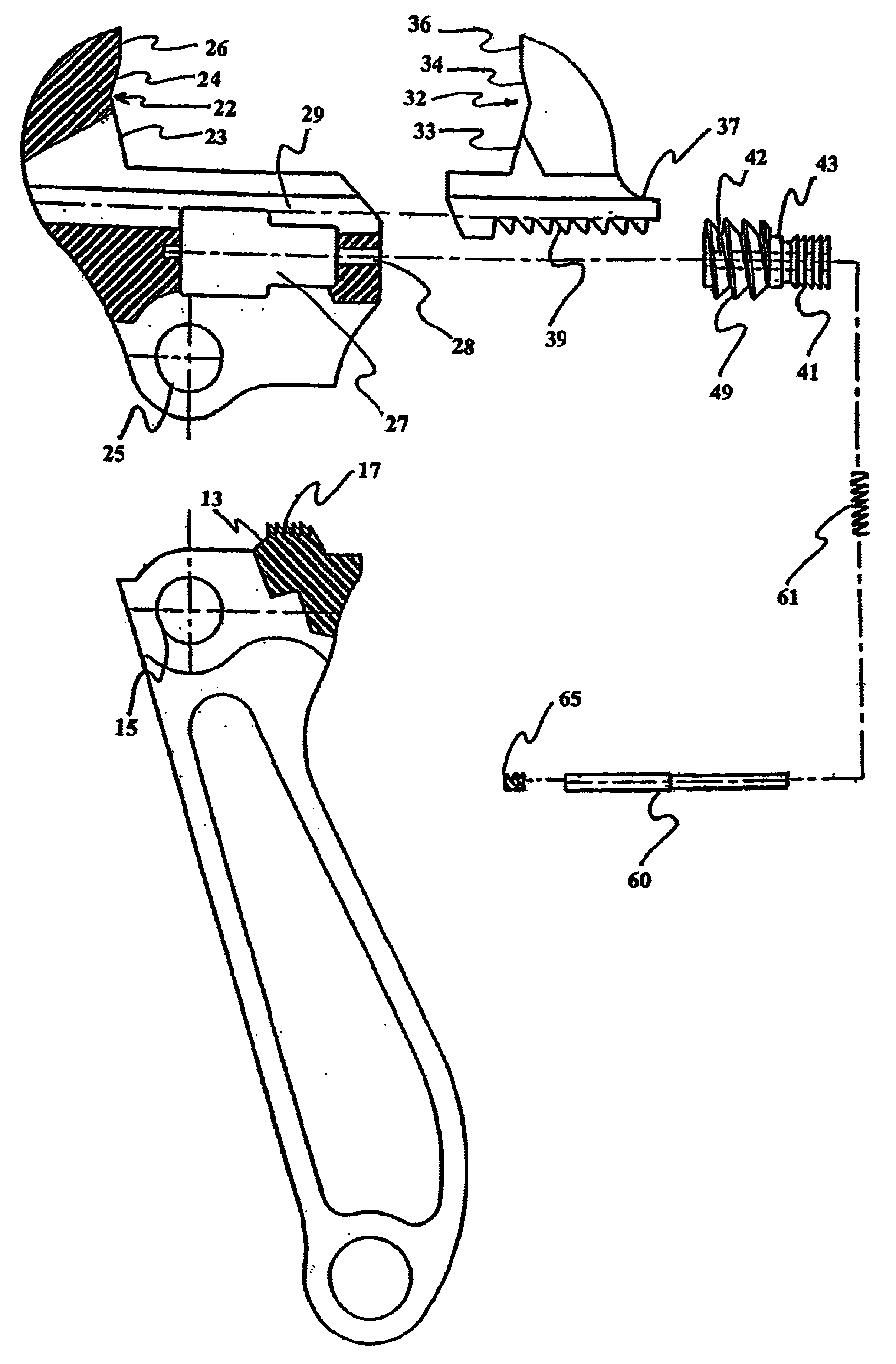
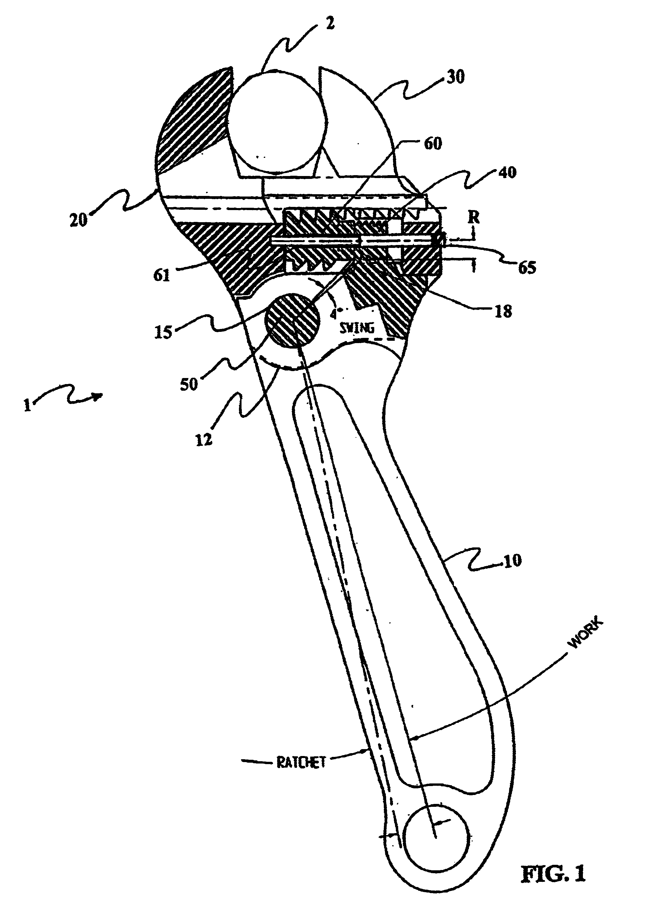
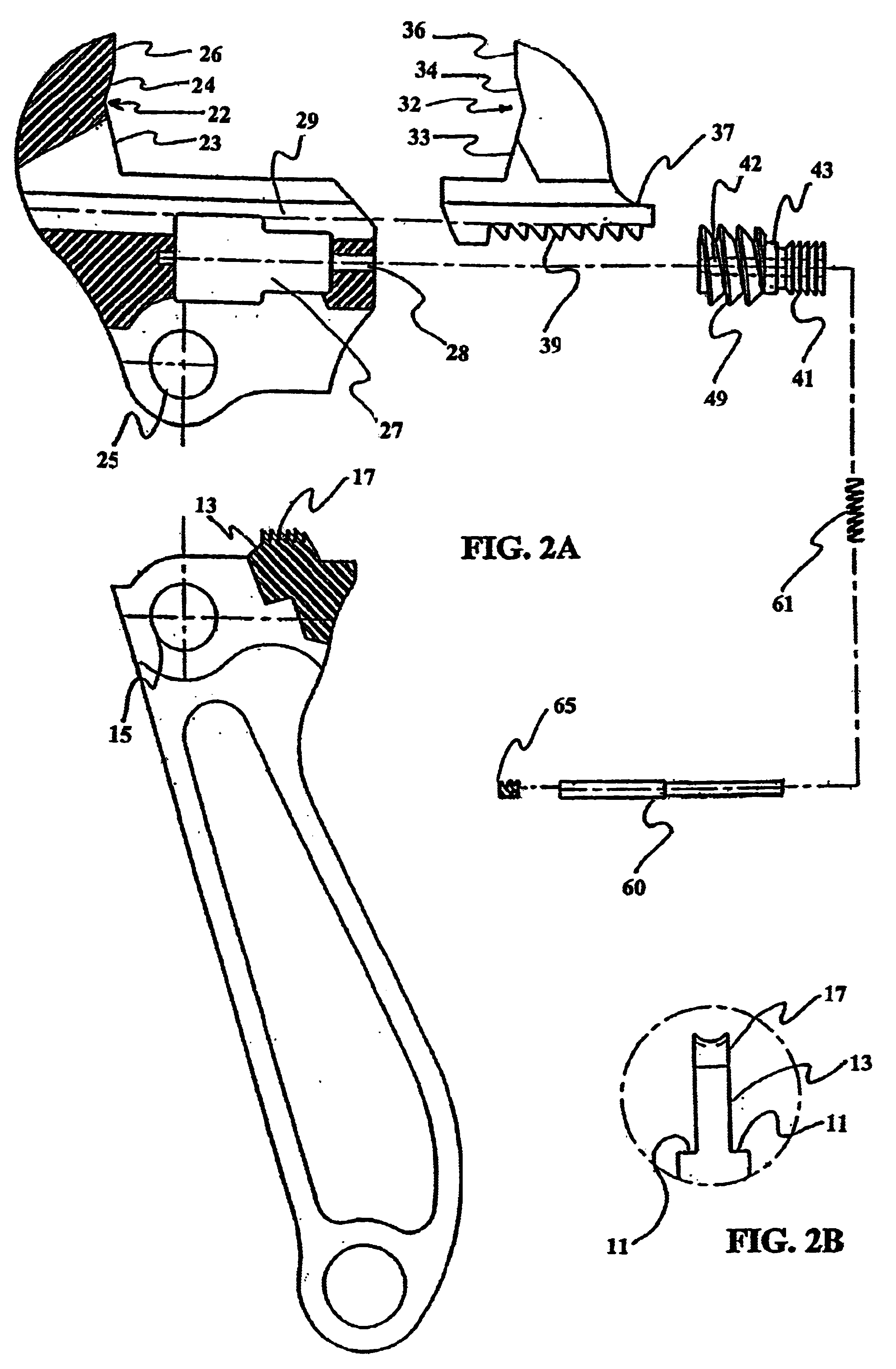
[0041]FIGS. 1-5 show an embodiment of a side-entry, adjustable ratcheting wrench assembly. The wrench 1 includes a handle 10, a main tool body 20 that acts as a pivoting stationary jaw, a dynamic jaw 30, a spring-loaded worm gear 40, and a pivot pin 50.

[0042]The handle 10 has a shoulder 11 extending laterally in a width-wise direction, generally, on both the front and back sides of the handle so that the upper portion of the handle 10 is offset from both the front and back outer surfaces of the handle 10. The handle 10 has a pivot hole 15 that aligns with the pivot hole 25 of the main tool body 20 so that the pivot pin 50 connects the main body 20 to the handle 10 and allows the handle 10 to pivot in relation to the main tool body 20. The shoulder 11 has at least one portion 12 with an arc shape formed radially with respect to the pivot holes 15, 25. The shoulder 11 may have a different shape or a same shape respectively on the front and back surfaces of the handle 10. A series of b...


PUM


Abstract

A side-entry, adjustable, ratcheting wrench has a first jaw member having an interior portion, a second jaw member slidingly engaged with the first jaw member, a spool disposed in the interior portion of the first jaw member, the spool having a worm gear along a first lengthwise outer portion and a series of concentric grooves along a second lengthwise outer portion, the worm gear for adjustment of the second jaw member, and a handle having a series of first projections engaged with the concentric grooves when the wrench is at a working position and disengaged from the concentric grooves when the wrench is at a ratcheting position.

Description

BACKGROUND[0001]1. Field of the Invention[0002]The present invention relates to hand tools and associated fastening devices and, more particularly, to an improved open-end adjustable wrench as well as a system and method for conveniently, effectively, and with improved safety, loosening or tightening a bolt or like article having a polygonal head.[0003]2. Background of the Invention[0004]Many types of adjustable wrenches are well known in the art. For example, a crescent type wrench typically has an open-end, adjustable, parallel jaw configuration where the jaws are fit onto a bolt or a nut by means of a worm gear that drives a series of teeth formed integrally with a moveable jaw. By such an adjusting, a bolt or nut is secured between the moveable jaw and a stationary jaw.[0005]Open-end adjustable jaw wrenches may have a limited function in a tight work space if the bolt or nut can only be rotated a fraction of a turn before it is necessary to remove the wrench from the bolt or nut...

Claims


Application Information

Patent Timeline
Patent Type & Authority Patents(United States)
IPC IPC(8): B25B13/00B25B13/46B25B13/14B25B13/20
CPCB25B13/14B25B13/20B25B13/46
Inventor SLEPEKIS, PATRICK JON
Owner JANSSON MUNGER MCKINLEY & SHAPE LTD
Why Eureka
Eureka Blog
Learn More