
Borehole compensation system and method for a resistivity logging tool

a compensation system and resistivity logging technology, applied in the field of measuring instruments, can solve the problems of increasing the diameter of the borehole, introducing measurement errors, and needing to alternately energize two transmitters, and maximizing the signal to noise ratio, so as to improve the rate of borehole data acquisition.

Inactive Publication Date: 2005-11-01
WEATHERFORD TECH HLDG LLC
View PDF17 Cites 23 Cited by
  • Summary
  • Abstract
  • Description
  • Claims
  • Application Information

AI Technical Summary

Benefits of technology

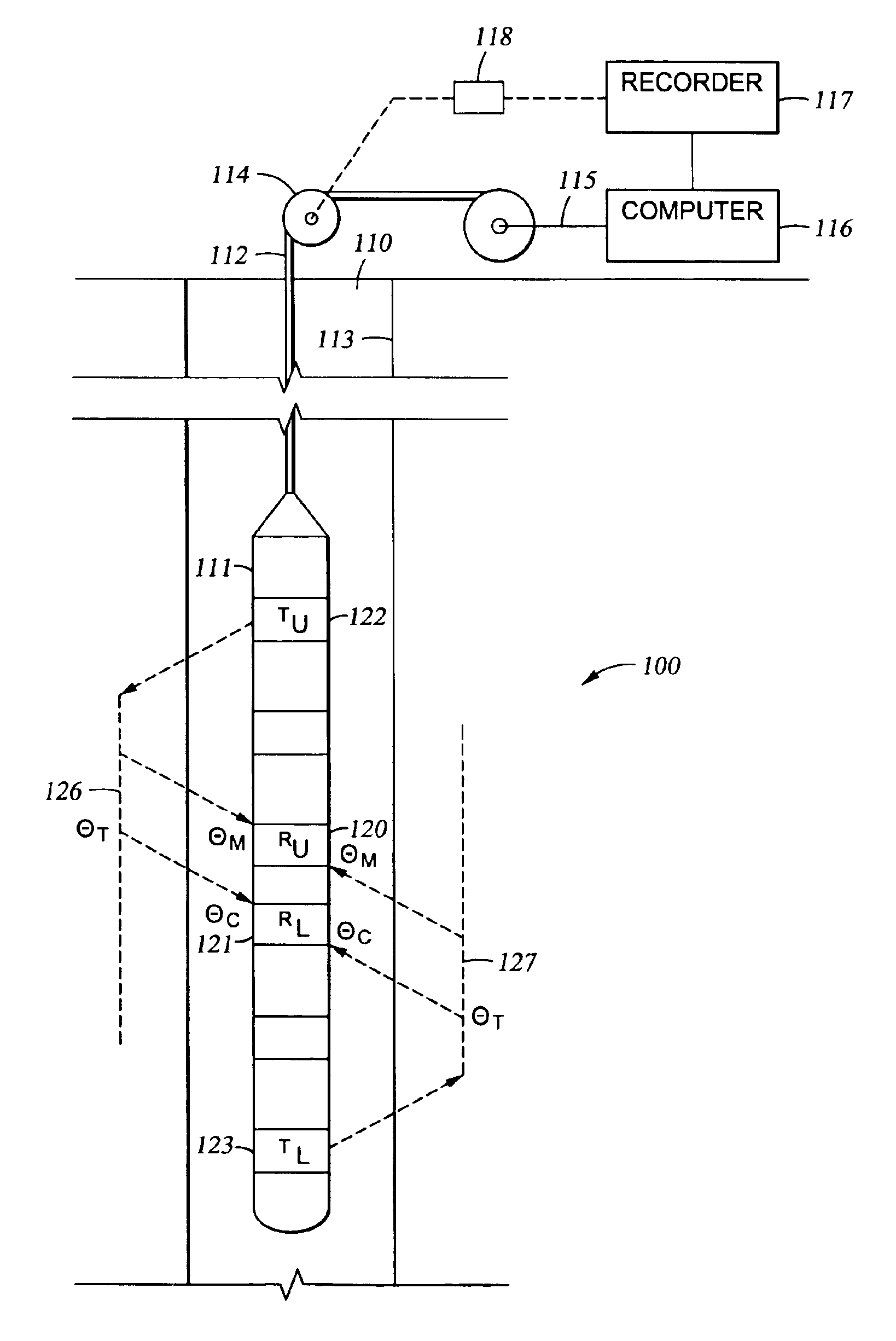
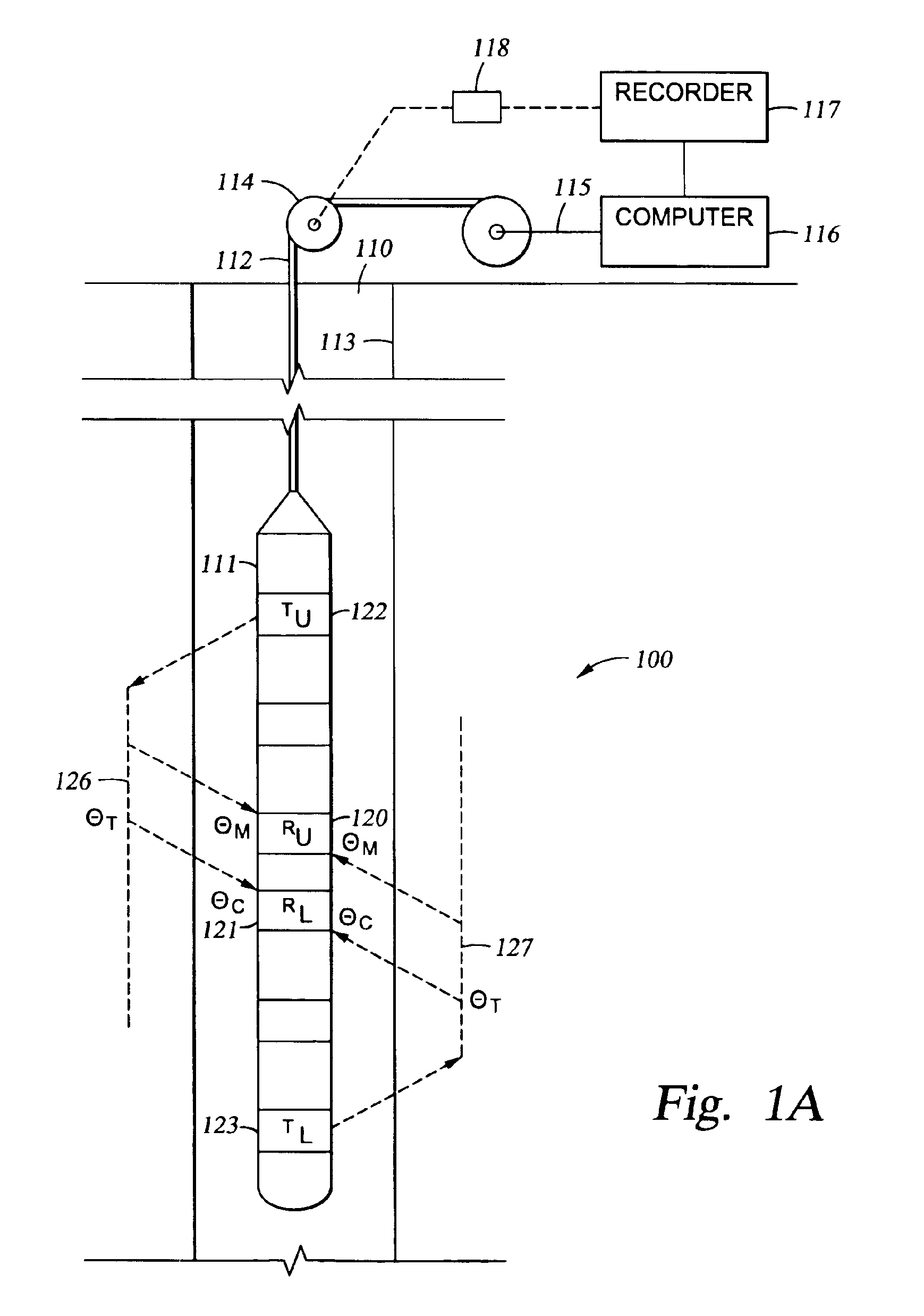
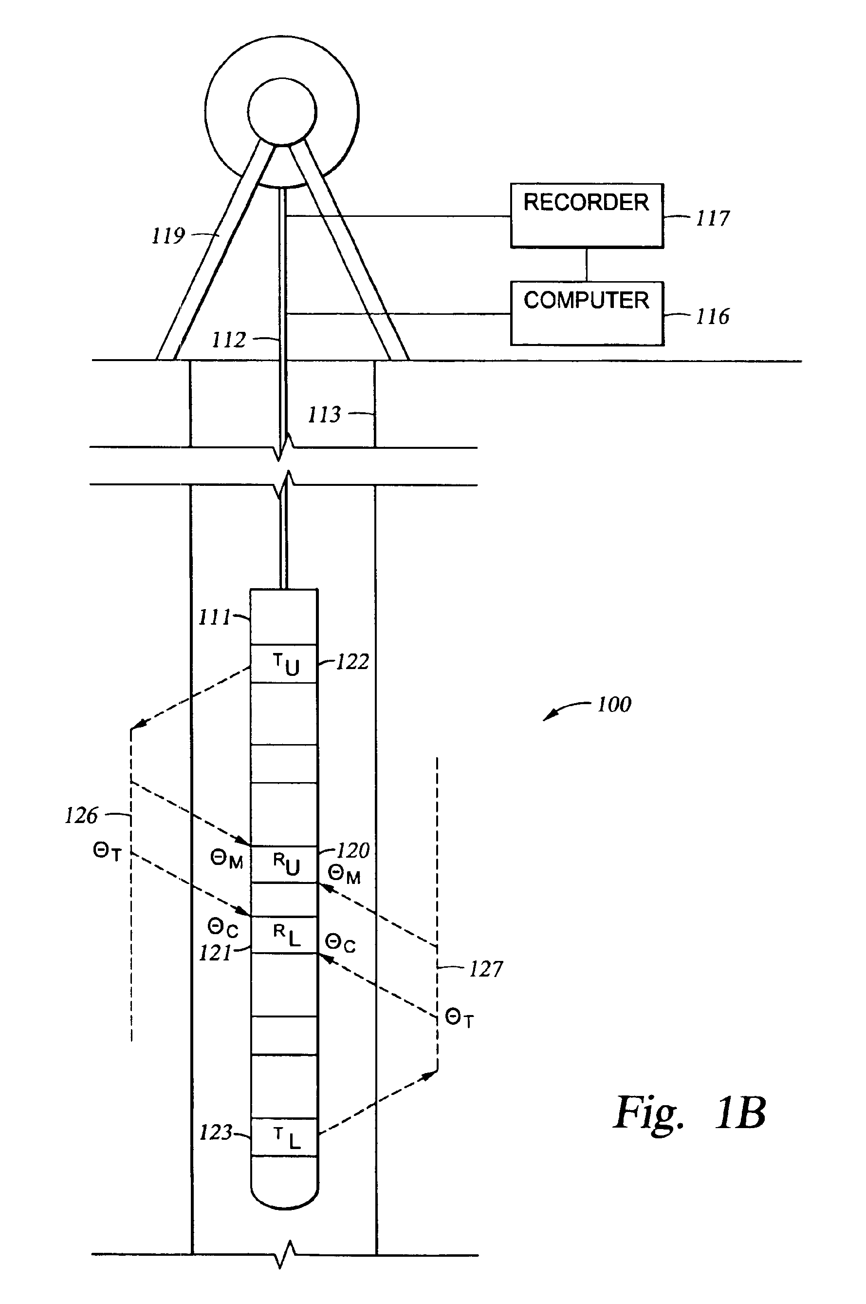
The present invention provides a system and method for borehole compensation that allows simultaneous transmissions of modulated signals using one or more transmitters and improves the rate of borehole data acquisition. The system and method maximize the signal to noise ratio by ensuring that the system continuously acquires data in each channel to the receiver. The apparatus for borehole compensation includes one or more transmitters, one or more receivers, a demodulation circuit, and a processing circuit. The processing circuit differentiates a phase difference signal and an amplitude attenuation signal from the demodulated signals, which provide data for borehole compensation.

Problems solved by technology

The increase in diameter can introduce errors in measurements due to additional local phase shift in, for example, one of the two receivers.
The major problem with existing borehole compensation methods is the need to alternately energize two transmitters.
However, using two transmitter coils alternately leads to errors in the form of incomplete compensation of borehole caving due to the time delay between sequential measurements, and the problem is amplified when a measurement tool is moving at high speed.
Moreover, the incomplete compensation problem is compounded when there are multiple transmitters for different radial depths of investigation.
The problems caused by alternate energizing of coils leads to significant slowing of the rate of data acquisition.
Further, the alternate energizing leads to errors in the form of incomplete compensation of borehole caving due to the time delay between sequential measurements and lowered signal to noise ratios due to the starting and stopping (i.e., duty cycle) of the transmitters.
Errors are magnified by the time delays when drilling rates are high.
Also, the multiplexing slows the rate of data acquisition.

Method used


Image

  • Borehole compensation system and method for a resistivity logging tool
  • Borehole compensation system and method for a resistivity logging tool
  • Borehole compensation system and method for a resistivity logging tool

Examples


Embodiment Construction

[0023]The following is intended to provide a detailed description of an example of the invention and should not be taken to be limiting of the invention itself. Rather, any number of variations may fall within the scope of the invention that is defined in the claims following the description.

[0024]Overview

[0025]Embodiments of the borehole compensation system and method employ a novel simultaneous multiplexing method employing frequency encoding. According to one embodiment, individual measurements are made at the same frequency, thereby avoiding errors due to different phase-shifts in the sensor coil and circuits that can be as significant as differences in the received signals due to borehole size variations. Another embodiment is directed to encoding a signal frequency Fo in a plurality of methods that distinguish the signal frequency from another signal.

[0026]Structure and Methodology

[0027]One embodiment is directed to using amplitude modulation. More specifically, the embodiment...


PUM


Abstract

System and method for borehole compensation. The method includes simultaneously transmitting at least two modulated signals from one or more transmitters; receiving the at least two modulated signals by at least one receiver; and processing the received at least two modulated signals to determine a phase difference and an amplitude attenuation of the transmitted modulated signals, the processing providing borehole compensated data.

Description

CROSS-REFERENCE TO RELATED APPLICATIONS[0001]This is a continuation of application U.S. Ser. No. 10 / 293,708 filed on Nov. 13, 2002 now U.S. Pat. No. 6,765,385. U.S. patent application Ser. No. 10 / 293,708 claims benefit of U.S. provisional application No. 60 / 350,590, filed Nov. 13, 2001. All of the above referenced U.S. patent applications are hereby incorporated by reference in their entireties.BACKGROUND OF THE INVENTION[0002]1. Field of the Invention[0003]The present invention relates to measurement instruments, and, more particularly, to a method and apparatus for measuring borehole characteristics.[0004]2. Description of the Related Art[0005]Resistivity logging tools are instruments used in operations in boreholes that are drilled into underground rock formations in the search for oil, gas, or minerals. Resistivity logging tools measure the electrical conductivity of the rock formations accessible from the borehole, and more particularly, perform multiple simultaneous measuremen...

Claims


Application Information

Patent Timeline
Patent Type & Authority Patents(United States)
IPC IPC(8): G01V3/30G01V3/18
CPCG01V3/30
Inventor SINCLAIR, PAUL L.SPRINGER, TOM
Owner WEATHERFORD TECH HLDG LLC
Learn More