
High-speed interconnection link having automated lane reordering

a high-speed interconnection and automatic technology, applied in the direction of electrical equipment, channel dividing arrangements, baseband system details, etc., can solve the problems of increasing speed, severe testing of system capacity limits, and increasing performance insufficien

Active Publication Date: 2005-11-01
HEWLETT-PACKARD ENTERPRISE DEV LP
View PDF12 Cites 110 Cited by
  • Summary
  • Abstract
  • Description
  • Claims
  • Application Information

AI Technical Summary

Benefits of technology

[0022]The problems noted above are solved in large part by a high speed multi-lane interconnection link that automatically detects if the lanes in the link have been reordered and corrects the order of the lanes if the lanes are not in the correct order. In one embodiment, the link includes transmitter and a receiver. The receiver is configured to receive a plurality of lanes and includes a receiver logic circuit configured to receive signals from each of the plurality of lanes. Lane misordering is corrected during a training sequence in which a first training sequence and a second training sequence are bilaterally transmitted between the transmitter and receiver. The training sequences are comprised of data sequences of equal length that are transmitted through each of the lanes in the link. The receiver monitors the training sequence for symbols that are unique to each lane and if an unexpected symbol is detected in the lane, thereby implying that a lane misorder has occurred, the receiver logic circuit will correct the order of the lanes. The link further comprises a transm...

Problems solved by technology

Internet and electronic commerce has grown to the point where demands placed on existing computer systems are severely testing the limits of system capacities.
Where this performance increase in inadequate, high performance systems have been designed with multiple processors and clustered architecture.
The demands created by these growing networks and increasing speeds are straining the capabilities of existing Input / Output (I / O) architecture.
It is apparent that the conventional PCI bus architecture is not keeping pace with the improvements of the surrounding hardware.
The PCI bus is quickly becoming the bottleneck in computer networks.
While this is indeed an improvement over the existing PCI standard, it is expected that the PCI-X bus architecture will only satisfy I / O performance demands for another two or three years.
In addition to the sheer bandwidth limitations of the PCI bus, the shared parallel bus architecture used in PCI creates other limitations which affect its performance.
Since the PCI bus is shared, there is a constant battle for resources between processors, memory, and peripheral devices.
First, it uses a differential pair of serial signal carriers, which drastically reduces conductor count.
At these kinds of bandwidths and transmission speeds, a host of complications which affect signal integrity may arise in the physical layer of a network protocol.
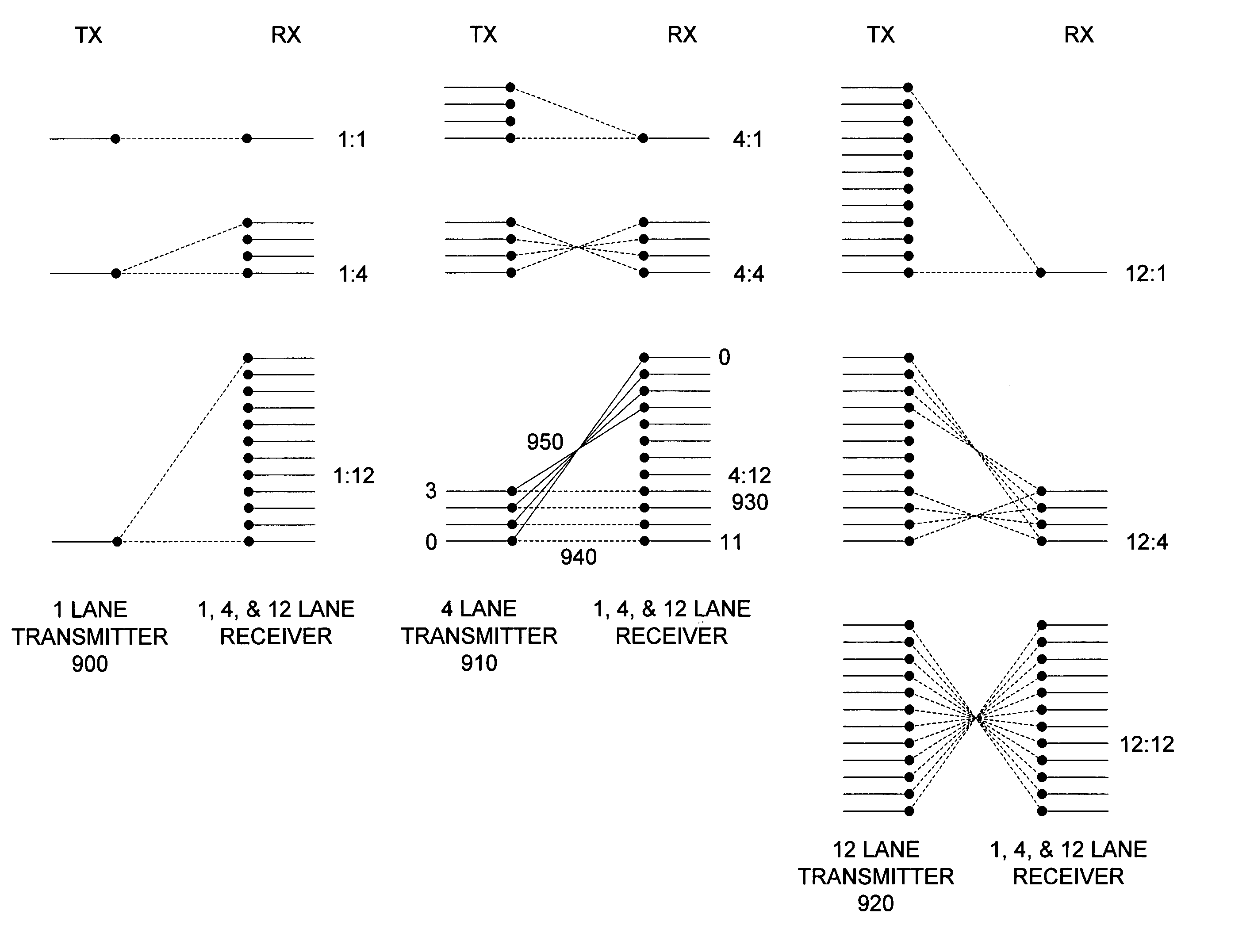
Where multiple lanes are used to transmit serial binary signals, examples of potential problems include the reordering of the lanes and skew.
Skew results from different lane lengths or impedances.
Even in the simplest case involving a single differential wire pair, a potential problem exists in the routing of the differential wire pair.
However, matched delay or matched length cabling is more expensive because of the manufacturing precision required.
It is often impractical to correct crossed differential pairs because one trace passes through two vias to “cross under” the other trace.
The vias introduce a substantial time delay, thereby causing data skew.
The above design considerations clearly make physical layer (i.e., cables, backplanes) manufacturing a difficult venture in high clock frequency systems.
Design costs and manufacturing costs are drastically increased due to the need to alleviate these types of problems.

Method used


Image

  • High-speed interconnection link having automated lane reordering
  • High-speed interconnection link having automated lane reordering
  • High-speed interconnection link having automated lane reordering

Examples


Embodiment Construction

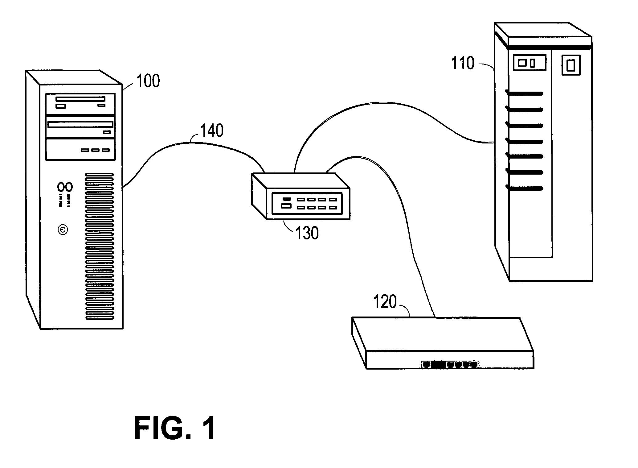
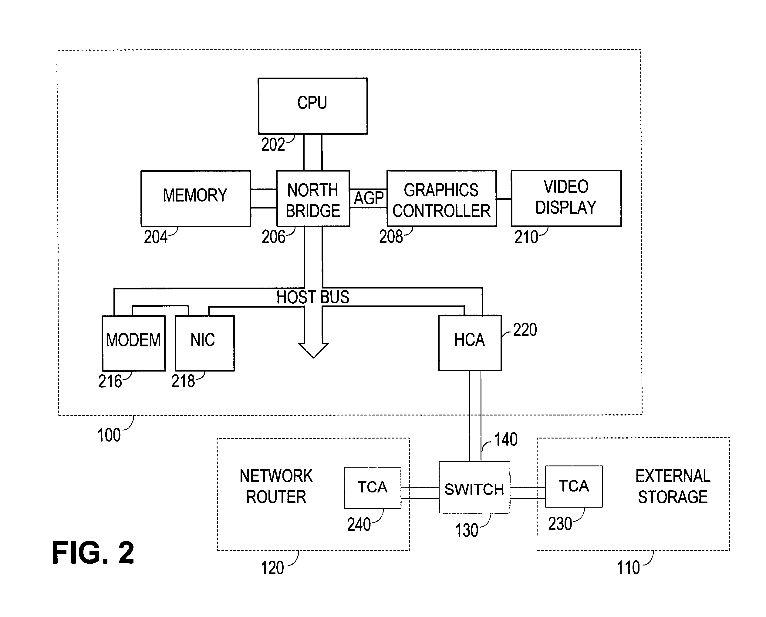
[0037]FIG. 1 shows an example of a computer network representing a preferred embodiment, in which a central computer 100 is coupled to an external storage tower 110 and a network router 120 via a multiservice switch 130. Storage tower 110 may be internally connected by a Fibre Channel, SCSI, or any suitable storage network. Network router may be connected to a LAN (local area network) or ISDN (Integrated Services Digital Network) network or it may provide a connection to the internet via a suitable ATM (asynchronous transfer mode) network. It should be appreciated that any number of computers, servers, switches, hubs, routers, or any suitable network device can be coupled to the network shown in FIG. 1.

[0038]In the preferred embodiment shown in FIG. 1, the devices are connected via a point to point serial link 140. The serial link may comprise an even number of lanes or channels through which data is transmitted. Of the even number of lanes, half will transmit serial data in one dir...


PUM


Abstract

A multi-lane link that automatically detects if the lanes in the link have been reordered and corrects the order of the lanes. In one embodiment, the link includes a transmitter and a receiver. The receiver is configured to receive a plurality of lanes and includes a receiver logic circuit configured to receive signals from each of the plurality of lanes. Lane misordering is corrected during a training sequence in which a first training sequence and a second training sequence are bilaterally transmitted between the transmitter and receiver. The receiver monitors the training sequence for symbols that are unique to each lane and if an unexpected symbol is detected in the lane, the receiver logic circuit will correct the order of the lanes. The link further comprises a transmitter logic circuit configured to transmit signals to the lanes. The transmitter logic circuit is configured to reorder the sequence of the signals transmitted to the lanes if the transmitter does not detect a response from the receiver. The transmitter logic circuit may consist of a bank of multiplexers configured to transmit a selected one of two input signals to be transmitted through a lane. Similarly, the receiver logic circuit may comprises a bank of multiplexers configured to transmit a selected one of two input signals received from a lane. The unique lane identifiers symbols are preferably insensitive to binary inversion and are preferably 10-bit symbols compatible with an 8B / 10B encoding scheme.

Description

CROSS-REFERENCE TO RELATED APPLICATIONS[0001]Not applicable.STATEMENT REGARDING FEDERALLY SPONSORED RESEARCH OR DEVELOPMENT[0002]Not applicable.BACKGROUND OF THE INVENTION[0003]1. Field of the Invention[0004]The present invention generally relates to high bandwidth interconnections for use in networking environments such as local area networks (LAN), wide area networks (WAN) and storage area networks (SAN). More specifically, it relates to a method of correcting lane reversal in signals resulting from varying paths and routing requirements in multiple, parallel signal carriers.[0005]2. Description of Related Art[0006]Internet and electronic commerce has grown to the point where demands placed on existing computer systems are severely testing the limits of system capacities. Microprocessor and peripheral device performances have improved to keep pace with emerging business and educational needs. For example, internal clock frequencies of microprocessors have increased dramatically, f...

Claims


Application Information

Patent Timeline
IPC IPC(8): H04J3/16H04L25/14
CPCH04L25/14
Inventor BUNTON, WILLIAM P.KRAUSE, JOHNWHITESIDE, PATRICIA L.
Owner HEWLETT-PACKARD ENTERPRISE DEV LP
Learn More