Printer and feeding control method
a technology of feeding control and printing machine, which is applied in printing, other printing apparatus, etc., can solve the problems of periodic gradation unevenness, black and white streaks are likely to appear in recorded images, and gradation unevenness, so as to reduce the time for calculating the correction value
- Summary
- Abstract
- Description
- Claims
- Application Information
AI Technical Summary
Benefits of technology
Problems solved by technology
Method used
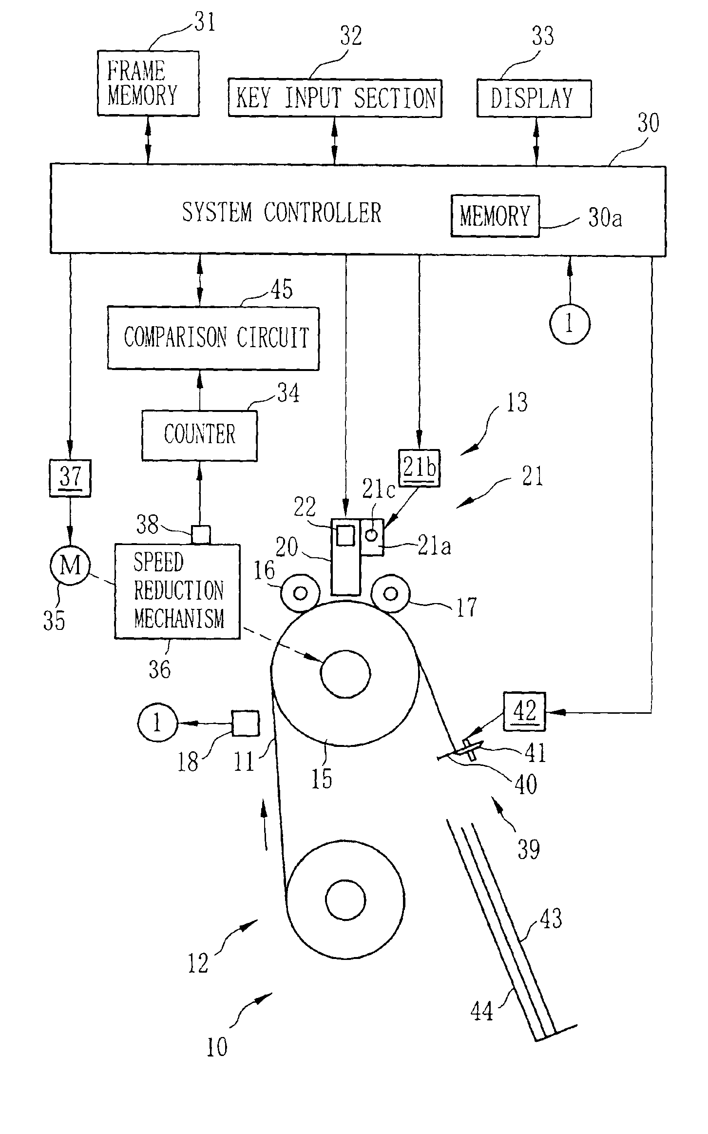
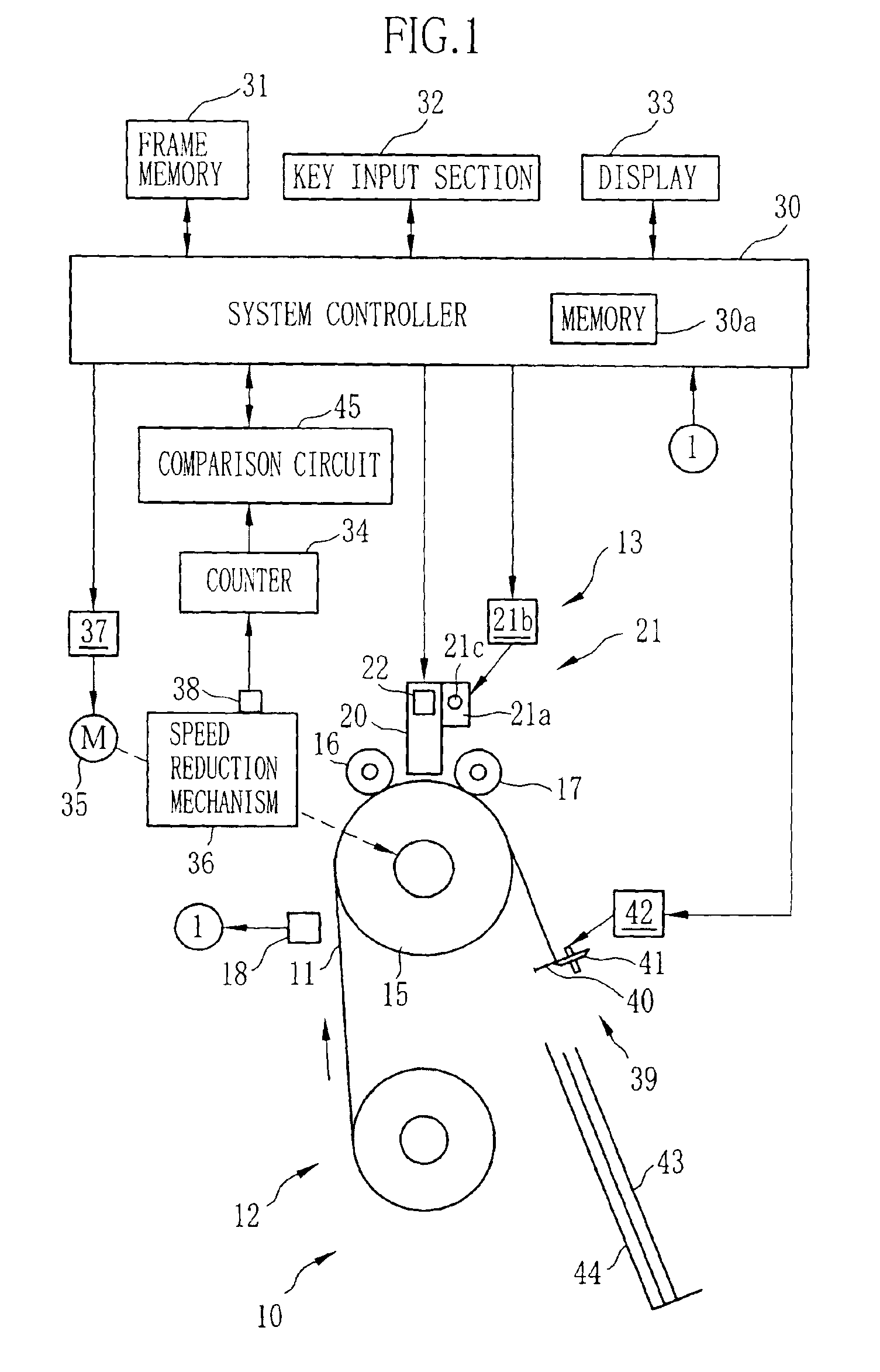
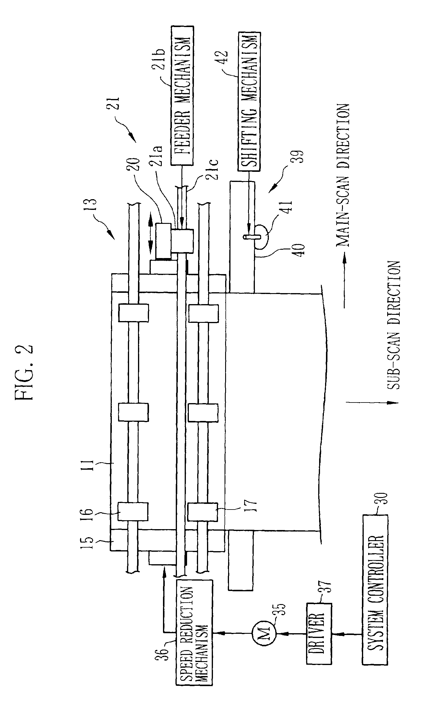
Image

Examples
example
[0059]An experiment is carried out for verifying the effect of the above embodiment.
[0060]In FIG. 8, although ink jet head 61 has nozzles of 4 colors, Y, M, C, and K, only nozzle 62 of one color is shown (for not making the figure complicated). HP1 represents a position (a head position) of the ink jet head 61 in the sub-scan direction during the first recording (first scanning) in the main-scan direction. Each of HP2-HP16 represents the position of the ink jet head 61 in the sub-scan direction during 2nd to 16th scanning. Note that the head positions HP1-HP16 are shifted in the main-scan direction in the figure not to make the figure unclear by overlaying HP1-HP16 in the same position in the main-scan direction.
[0061]In the example, the ink jet head 20 has 92 nozzles 62 in the sub-scan direction with the nozzle pitch PN of 141.1 μm. The basic feeding amount B is 811.4 μm. A diameter of the dot recorded on the recording paper 11 is 30-60 μm. A pitch p between the dots is 35.3 μm. Fe...
PUM
 Abstract
Description
Claims
Application Information
 - R&D
- Intellectual Property
- Life Sciences
- Materials
- Tech Scout
- Unparalleled Data Quality
- Higher Quality Content
- 60% Fewer Hallucinations
Browse by: Latest US Patents, China's latest patents, Technical Efficacy Thesaurus, Application Domain, Technology Topic, Popular Technical Reports.
© 2025 PatSnap. All rights reserved.Legal|Privacy policy|Modern Slavery Act Transparency Statement|Sitemap|About US| Contact US: help@patsnap.com