
Solenoid valve having manually-operated device

a solenoid valve and manual operation technology, which is applied in the direction of valve details, valve arrangement, operating means/releasing devices, etc., can solve the problem of prone to sealing failure and achieve the effect of simple structur

Active Publication Date: 2005-11-01
SMC CORP
View PDF22 Cites 10 Cited by
  • Summary
  • Abstract
  • Description
  • Claims
  • Application Information

AI Technical Summary

Benefits of technology

[0010]It is another technical object of the invention to provide a solenoid valve having a manually-operated device capable of preventing a deviated load from being applied to the operating rod of the manually-operated device, and capable of preventing a seal failure from being generated.
[0013]Thus, it is possible to dispose the manually-operated device in the solenoid valve while avoiding a portion thereof constituted by a substrate or the like on which an electronic component such as a connector for electrical connection and a lamp is mounted, and it is possible to prevent a seal failure due to the deviated load from being generated.
[0017]With this structure, it is possible to connect the slide member and the operation rod to each other with a simple structure, and to transmit the driving force of the slide member to the operation rod precisely. Further, the operating member is reliably returned to the non-operation position by the spring.

Problems solved by technology

For this purpose, if the solenoid valve is made compact in size, there is a problem that portion of the solenoid valve constituted by a substrate or the like on which an electronic component such as a connector for electrical connection and a lamp is located at an installing position of the manually-operated device 205.
Therefore, deviated load is applied to the operating member 251 in a direction at right angles to its axial direction, and a sealing failure is prone to be generated when the operating member 251 is operated.

Method used


Image

  • Solenoid valve having manually-operated device
  • Solenoid valve having manually-operated device
  • Solenoid valve having manually-operated device

Examples


first embodiment

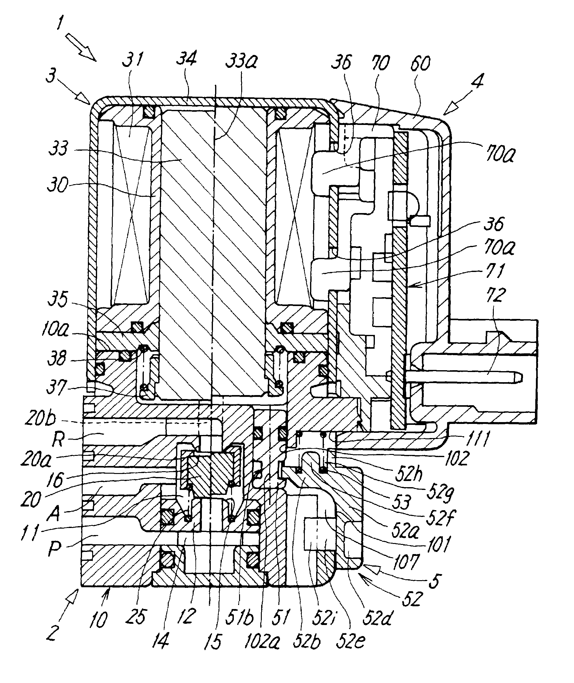
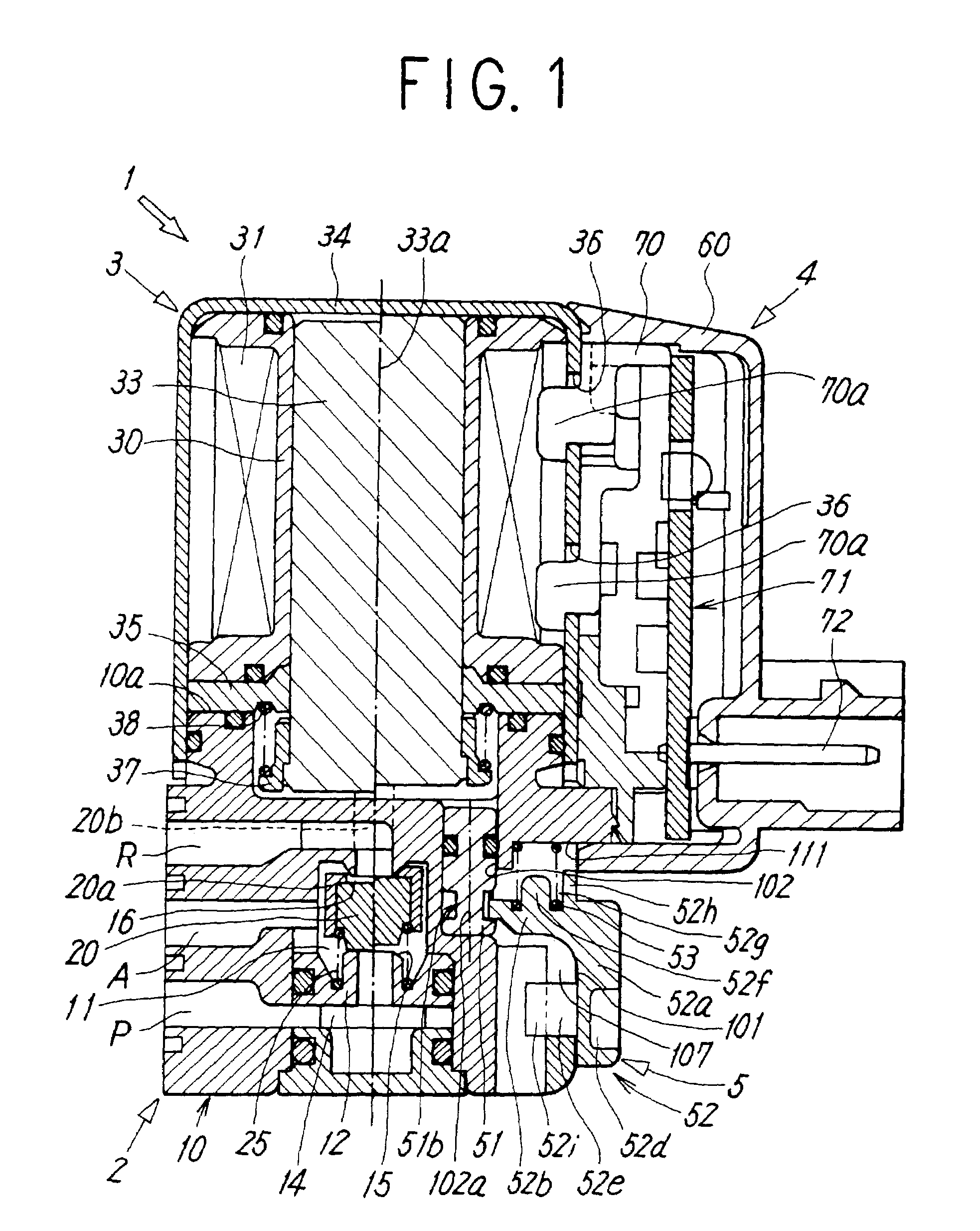
[0033]FIGS. 1 to 4 shows a solenoid valve having a manually-operated device. According to the present invention, as shown in FIG. 1, this solenoid valve 1 includes a main valve 2 having a valve member 20 which switches over flow paths by approaching and separating from valve seats 15 and 16 in a valve casing 10, and a solenoid operating portion 3 which drives the valve member 20 toward and away from the valve seats 15 and 16. A terminal casing 4 for energizing the solenoid operating portion 3 is provided from the solenoid operating portion 3 to the main valve 2 along outsides thereof.

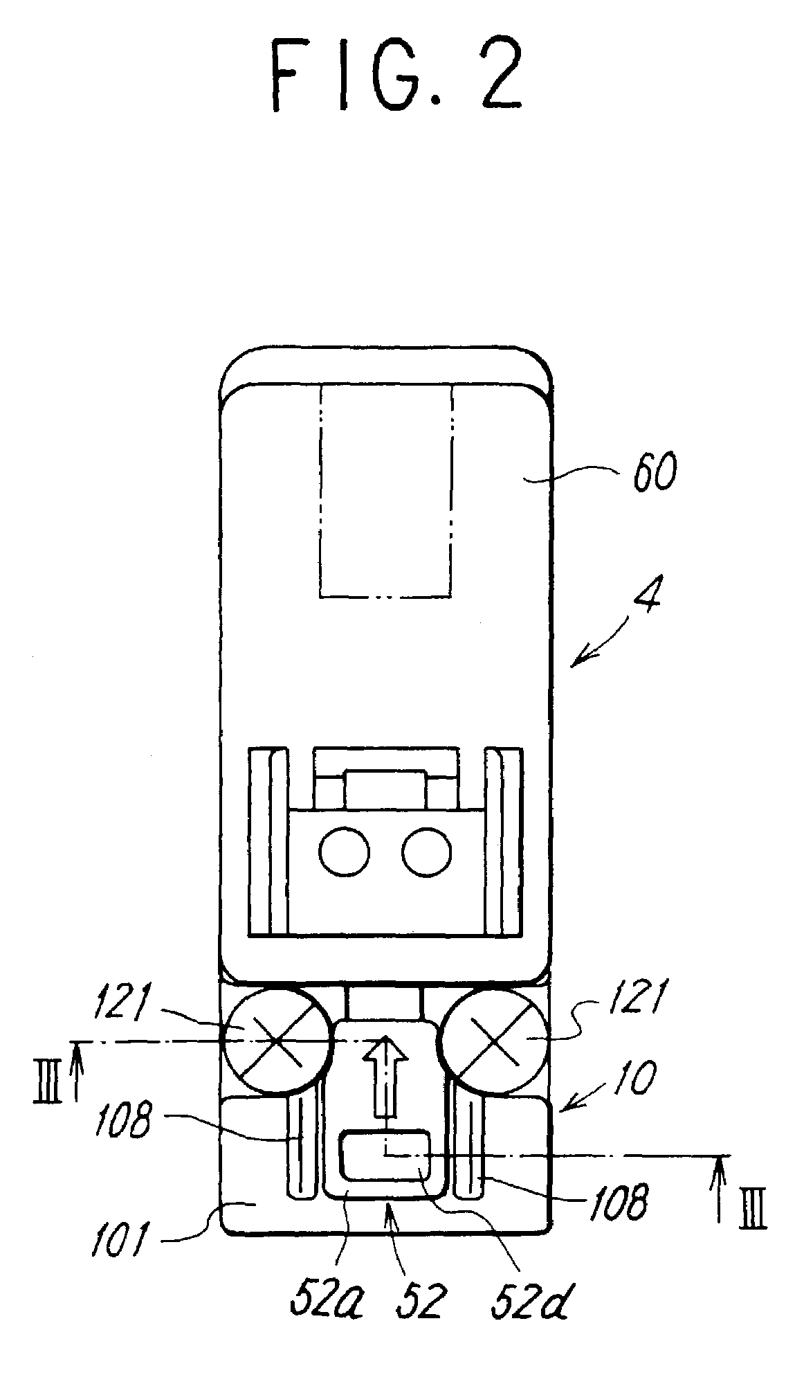
[0034]As shown in FIGS. 1 and 4, a manually-operated device 5 used for the solenoid valve 1 includes an operation rod 51 which abuts against an end surface of a movable iron core 33 of the solenoid operating portion 3 for pushing the movable iron core 33 in its axial direction, and an operating member 52 for operating the operation rod 51. The operating member 52 is movably mounted to an outer mounting ...

second embodiment

[0068]In the second embodiment, as shown in FIGS. 10A and 10B, turning-limited positions in a left direction and a right direction of the second member 153 are an OFF position and an ON position of the operation rod, respectively.

[0069]As shown in FIG. 7, the first member 152 and the second member 153 constituting the operating member 52 of the second embodiment is mounted to the operating portion mounting opening 105 of the valve casing 10. At that time, the spring 53 pushes the second member 153 through the first member 152 in a direction opposite from the movable iron core 33. Therefore, in the OFF position of the operation rod 51 shown in FIG. 10A, the flat wall portion 153g of the cam-acting portion 153b is pushed against the end wall 115 of the operating portion mounting opening 105 as shown in FIG. 5.

[0070]In this state, if the second member 153 is turned rightward (clockwise direction) utilizing the turning groove 153e, the cam-acting portion 153b which is coaxial with the r...


PUM


Abstract

A solenoid valve includes a main valve having a valve member which switches over flow paths by contacting with and separating from valve seats in a valve casing, a solenoid operating portion to drive the valve member, and a manually-operated device including an operation rod air-tightly and slidably accommodated in a rod-insertion hole provided in the valve casing and abuts against an end surface of a movable iron core to push the movable iron core in its axial direction, and an operating member movably mounted to a mounting surface of the valve casing to drive the operation rod.

Description

TECHNICAL FIELD TO WHICH THE INVENTION BELONGS[0001]The present invention relates to a solenoid valve having a manually-operated device for manually operating a valve member when the valve member closes a valve seat due to an accident such as a power failure.PRIOR ART[0002]As shown in FIGS. 11 and 12, a solenoid valve having a manually-operated device for manually opening a valve seat when a valve member closes the valve seat due to an accident such as a power failure is known.[0003]That is, a solenoid valve having a manually-operated device shown in FIG. 11 comprises a main valve 202 having valve members 220, 221 which switch over flow paths by contacting with and separating from valve seats 215, 216 in a valve casing 210, and a solenoid operating portion 203 which drives the valve members 220, 221 toward and away from the valve seats 215, 216. The valve casing 210 is provided with a through hole 250 extending from its surface to an end of the movable iron core 233 of the solenoid ...

Claims


Application Information

Patent Timeline
IPC IPC(8): F16K31/06F16K31/11
CPCF16K31/0627F16K31/05
Inventor MATSUMOTO, TAKUMIISHIKAWA, MAKOTO
Owner SMC CORP
Learn More