
Air intake apparatus and manufacturing method therefor

a technology of air intake and manufacturing method, which is applied in the direction of intake silencers for fuel, combustion-air/fuel-air treatment, machines/engines, etc., can solve the problems of noise generated in the intake passage portion, pressure leakage from this unsealed part, and noise generated by the vibration of the porous member itself, etc., and achieve the effect of low cos

Inactive Publication Date: 2005-11-01
TOYODA GOSEI CO LTD
View PDF2 Cites 25 Cited by
  • Summary
  • Abstract
  • Description
  • Claims
  • Application Information

AI Technical Summary

Benefits of technology

[0015]The invention is accomplished in consideration of the aforementioned circumstances. Accordingly an object of the invention is to provide an air intake apparatus, which is adapted so that the outer edge of the opening is reliably sealed with the porous member, and which is manufactured at low cost regardless of the shape of the outer edge of the opening, and to provide a manufacturing method therefor.
[0017]According to the first method of the invention, the porous member is held by the holding portion in the temporarily fixing step. Thus, the opening can reliably be covered with the porous member without using any special jig.

Problems solved by technology

Incidentally, in this intake apparatus, noise is generated in the intake passage portion during air intake.
This noise leaks out of the intake apparatus from the introduction port, and propagates to the inside or outside of a passenger compartment.
That is, in the case where an outer edge of the opening is not reliably sealed with the porous member, and where a part directly communicating with the outside of the intake passage portion is provided in the opening, pressure leaks from this unsealed part.
On the contrary, noise due to vibrations of the porous member itself sometimes occurs.
Thus, it is sometimes difficult to securely place the porous member against the opening.
Therefore, this related method has problems in that a same porous-member receiving jig cannot be adapted to variously shaped intake apparatuses, and that the manufacturing cost of the apparatus thereof increases.
Thus, this related method has a problem in that because the placement position of the porous member cannot be corrected even when that of the porous member with respect to the opening is displaced, a manufacturing loss occurs, and that the manufacturing cost of the apparatus increases.

Method used


Image

  • Air intake apparatus and manufacturing method therefor
  • Air intake apparatus and manufacturing method therefor
  • Air intake apparatus and manufacturing method therefor

Examples


first embodiment

[0069

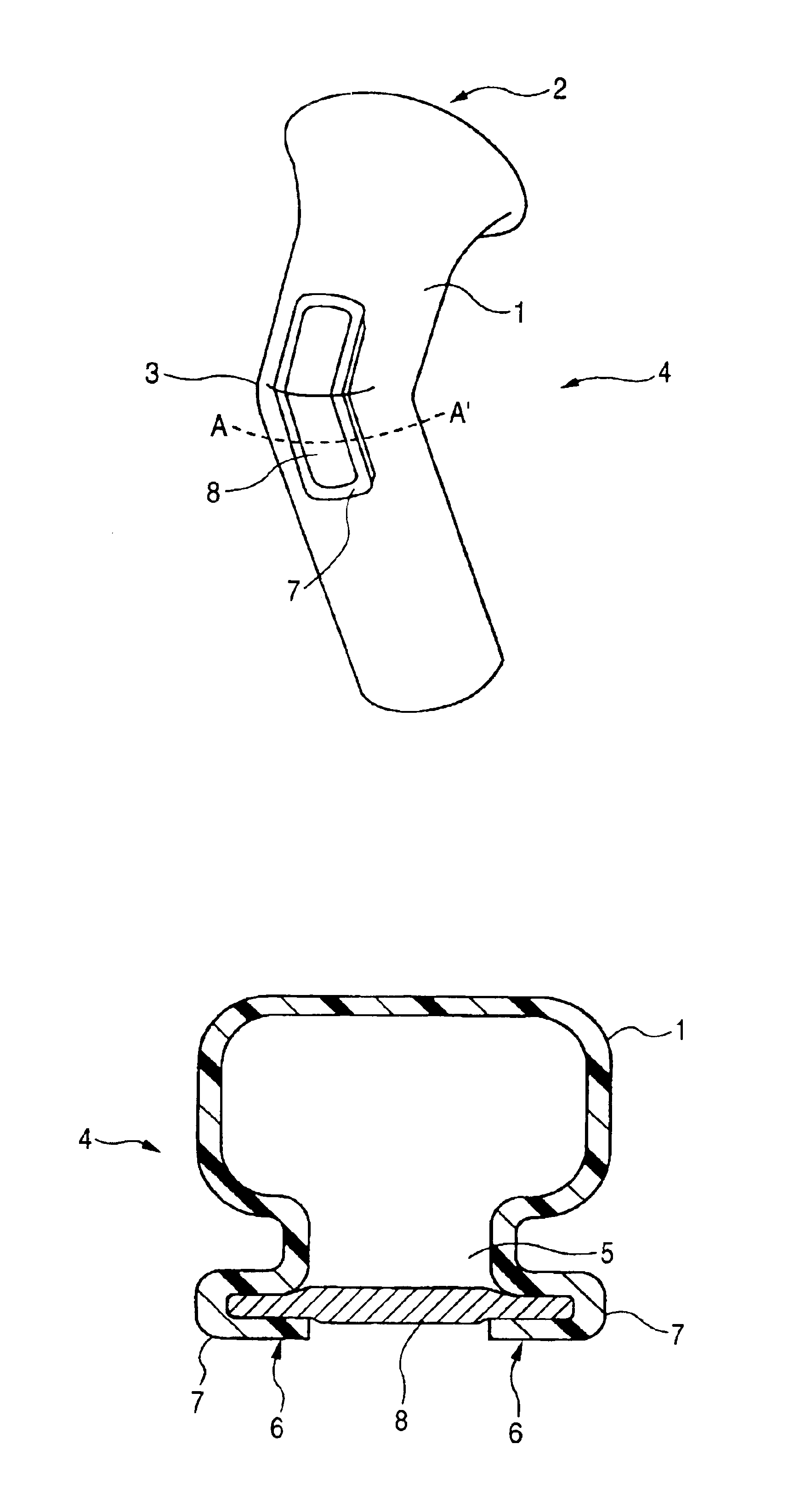
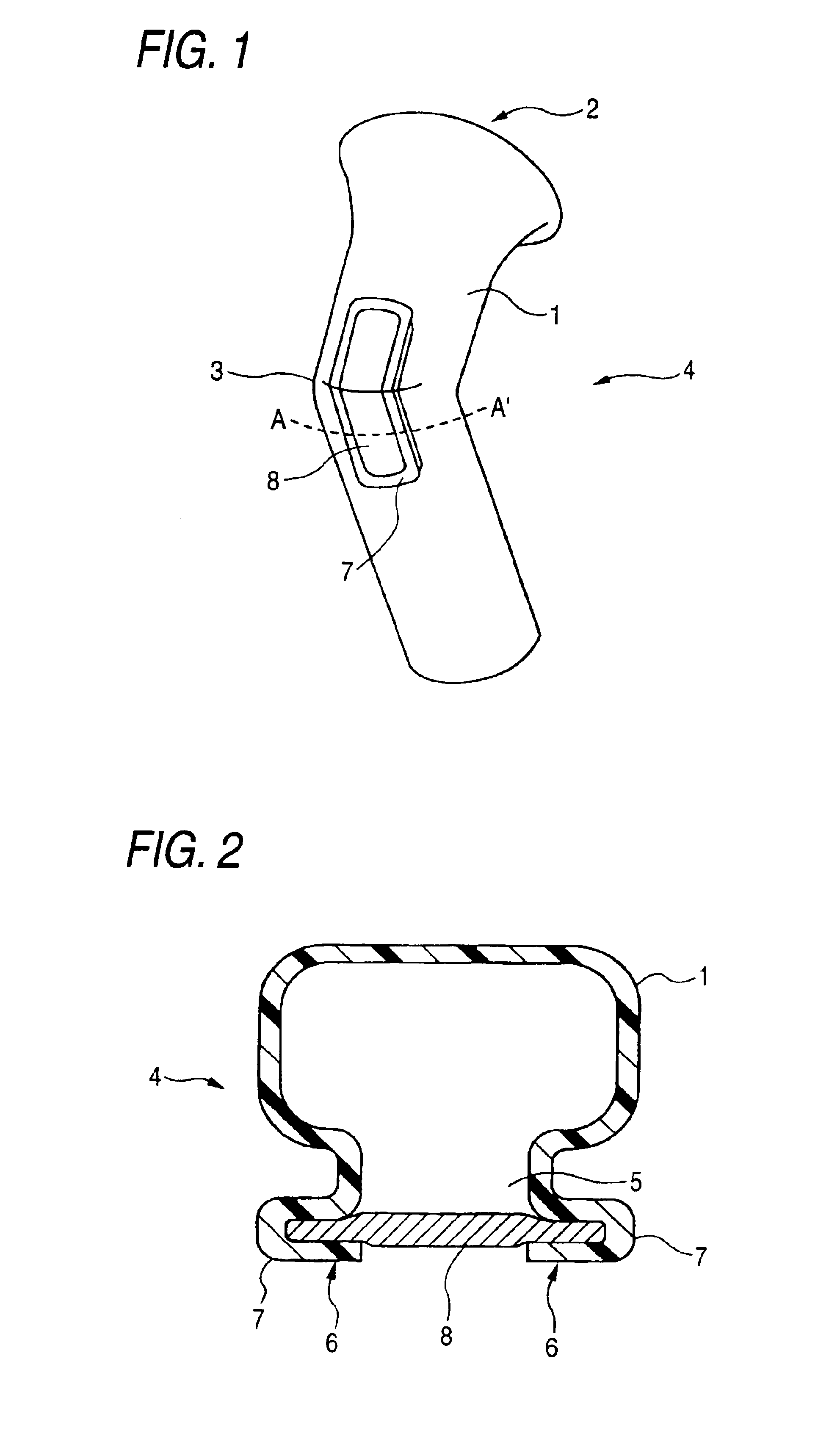
[0070]A first embodiment of the invention is an example of application of the method of manufacturing an air intake apparatus according to the invention to an air intake duct that is a part of an air intake passage portion of an automobile. Therefore, in the first embodiment, the opening and the porous member are disposed in this air intake duct. The air intake duct, in which the opening and the porous member are placed, is the air intake apparatus according to the invention. FIG. 1 is a schematic perspective view showing the air intake apparatus according to the first embodiment of the invention. FIG. 2 is a schematic cross sectional view taken along line A-A′ of FIG. 1.

[0071]In the first embodiment, an air intake duct 1 is formed into a curved shape in such a way as to have an introduction port 2 from which intake air is introduced. An opening 5 is provided in a curved surface 3 of this intake duct 1. A holding portion 7 protruding to the outside of the intake duct 1 is forme...

second embodiment

[0085

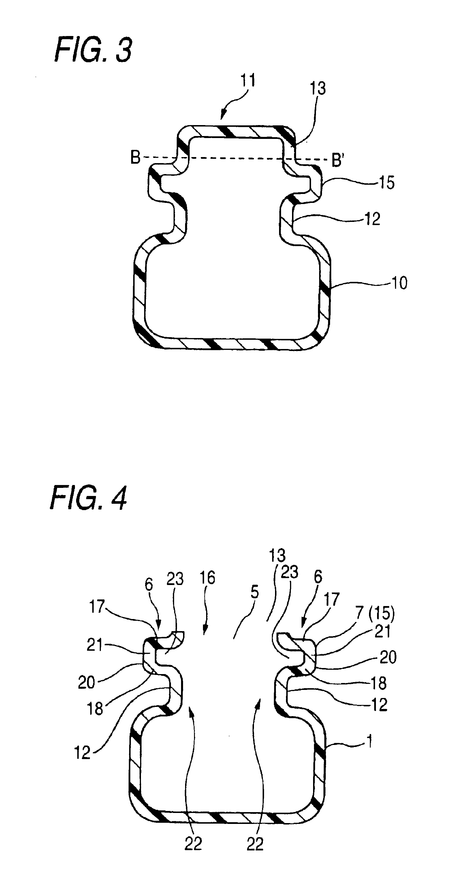
[0086]A method of manufacturing an air intake apparatus according to a second embodiment of the invention is similar to the method of manufacturing an air intake apparatus according to the first embodiment of the invention, except for the shape of the holding portion, and except that the porous member and the holding portion are partly welded to each other in the temporarily fixing step. The air intake apparatus according to the second embodiment has a shape similar to that of the air intake apparatus according to the first embodiment. FIGS. 8 to 12 are schematic views illustrating the method of manufacturing the air intake apparatus according to the second embodiment.

[0087]Holding-Portion Forming Step

[0088]First, an intake duct 31 is formed by resin blow molding. A parison (not shown) made of PP is formed, similarly as the parison used in the first embodiment. The formed parison is disposed in a blow molding die (not shown). Then, air is injected into the parison. Subsequently...

third embodiment

[0099

[0100]A method of manufacturing an air intake apparatus according to a third embodiment of the invention is similar to the method of manufacturing an air intake apparatus according to the first embodiment of the invention, except for the shape of the holding portion. The air intake apparatus according to the third embodiment has a shape similar to that of the air intake apparatus according to the first embodiment. FIGS. 13 to 15 are schematic views illustrating the method of manufacturing the air intake apparatus according to the third embodiment.

[0101]Holding-Portion Forming Step

[0102]First, an intake duct 58 is formed by resin blow molding. A parison (not shown) made of PP is formed, similarly as the parison used in the first embodiment. The formed parison is disposed in a blow molding die (not shown). Then, air is injected into the parison. Subsequently, the parison is cooled and solidified. Thus, a first molding product 60 of the intake duct 58 is molded. FIG. 13 is a view ...


PUM

PropertyMeasurementUnit
Flow rateaaaaaaaaaa
Diameteraaaaaaaaaa

Abstract

The manufacturing method for the air intake apparatus has a holding-portion forming step, a temporarily fixing step, and a joining step. In the holding-portion forming step, a holding portion is formed. In the temporarily fixing step, the porous member is held by the holding portion. In the joining step, the holding portion and the porous member are joined together. Thus, an air intake apparatus, in which the opening is reliably covered with the porous member, can be manufactured. In the air intake apparatus manufactured by this manufacturing method, a peripheral portion of the porous member is doubly sealed with the holding portion that is an outer edge part of the opening. Consequently, the opening is reliably covered with the porous member, so that intake noise is reliably reduced.

Description

[0001]The present application is based on Japanese Patent Application No. 2003-087657, which is incorporated herein by reference.BACKGROUND OF THE INVENTION[0002]1. Field of the Invention[0003]The present invention generally relates to an air intake apparatus serving as a passage for supplying air to an engine, and also relates to a manufacturing method therefor. More particularly, the invention relates to an air intake apparatus in which noise generated at the time of air intake is reduced, and to a manufacturing method therefor.[0004]2. Description of the Related Art[0005]In an air intake system of an engine, air taken in from an introduction port of an engine body is supplied to an engine body through an air intake passage portion connected from this introduction port to the engine body. This intake passage portion is provided with an air intake duct communicating with the introduction port. Generally, this intake passage portion is also provided with various intake members, such...

Claims


Application Information

Patent Timeline
IPC IPC(8): F02M35/10B60K13/02B29C65/56B29L31/30F02M35/12
CPCB29C65/568B29C66/83221F02M35/10321B29C66/532F02M35/1036B29C66/81425F02M35/10334B29C66/81423B29C66/727B29C66/7294B29C66/61B29C66/112B29C66/12441B29C66/135
Inventor KINO, HITOSHIIWAO, HIROSHI
Owner TOYODA GOSEI CO LTD
Learn More