
Fuel nozzle for a fossil fuel fired combustion arrangement

Active Publication Date: 2005-11-01
GENERAL ELECTRIC TECH GMBH
View PDF4 Cites 8 Cited by
  • Summary
  • Abstract
  • Description
  • Claims
  • Application Information

AI Technical Summary

Benefits of technology

The present invention provides a pulverized solid fuel nozzle with a pivotally mounted tip that allows for easy installation and de-installation of the nozzle. The nozzle tip is connected to the nozzle body through a latch interconnecting assembly and a pin that is inserted through the tip and the nozzle body. The pin has a traverse end and an inside end, and the engagement element can resist the withdrawal movement of the pin. The technical effect of this invention is to simplify the installation and maintenance of the pulverized solid fuel nozzle.

Problems solved by technology

Also, the apparatus includes an engagement element for resisting a withdrawal movement of the pin in a direction opposite to its traversing movement, the engagement element being reversibly movable between a deployed position in which the engagement element engages the pin to resist withdrawal movement of the pin in a direction opposite to its traversing movement and a non-deployed position in which resistance of withdrawal movement of the pin by the engagement element is insufficient to prevent withdrawal of the pin from the throughhole of the coal nozzle tip.

Method used


Image

  • Fuel nozzle for a fossil fuel fired combustion arrangement
  • Fuel nozzle for a fossil fuel fired combustion arrangement
  • Fuel nozzle for a fossil fuel fired combustion arrangement

Examples


Embodiment Construction

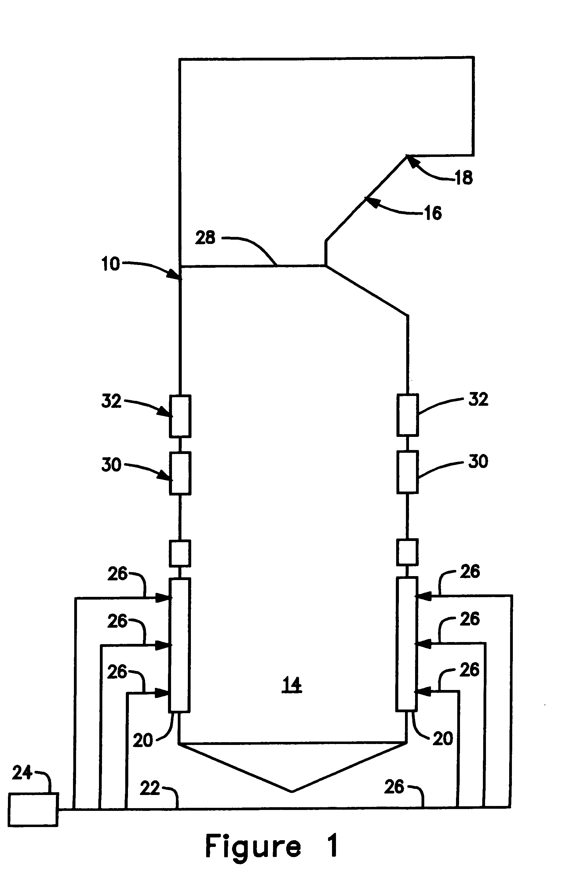
[0023]Referring now to FIG. 1, there is depicted therein a pulverized solid fuel-fired furnace 10 having a burner region 14 within which the combustion of pulverized solid fuel and air is initiated and a plurality of fuel compartments 12 through which the pulverized solid fuel is injected into the burner region 14. The hot gases that are produced from combustion of the pulverized solid fuel and air rise upwardly in the pulverized solid fuel-fired furnace 10 and give up heat to the fluid passing through the tubes (not shown in the interest of maintaining clarity of illustration in the drawing) that in conventional fashion line all four of the walls of the pulverized solid fuel-fired furnace 10. Then, the hot gases exit the pulverized solid fuel-fired furnace 10 through a horizontal pass 16 of the pulverized solid fuel-fired furnace 10, which in turn leads to a rear gas pass 18 of the pulverized solid fuel-fired furnace 10. Both the horizontal pass 16 and the rear gas pass 18 commonly...


PUM


Abstract

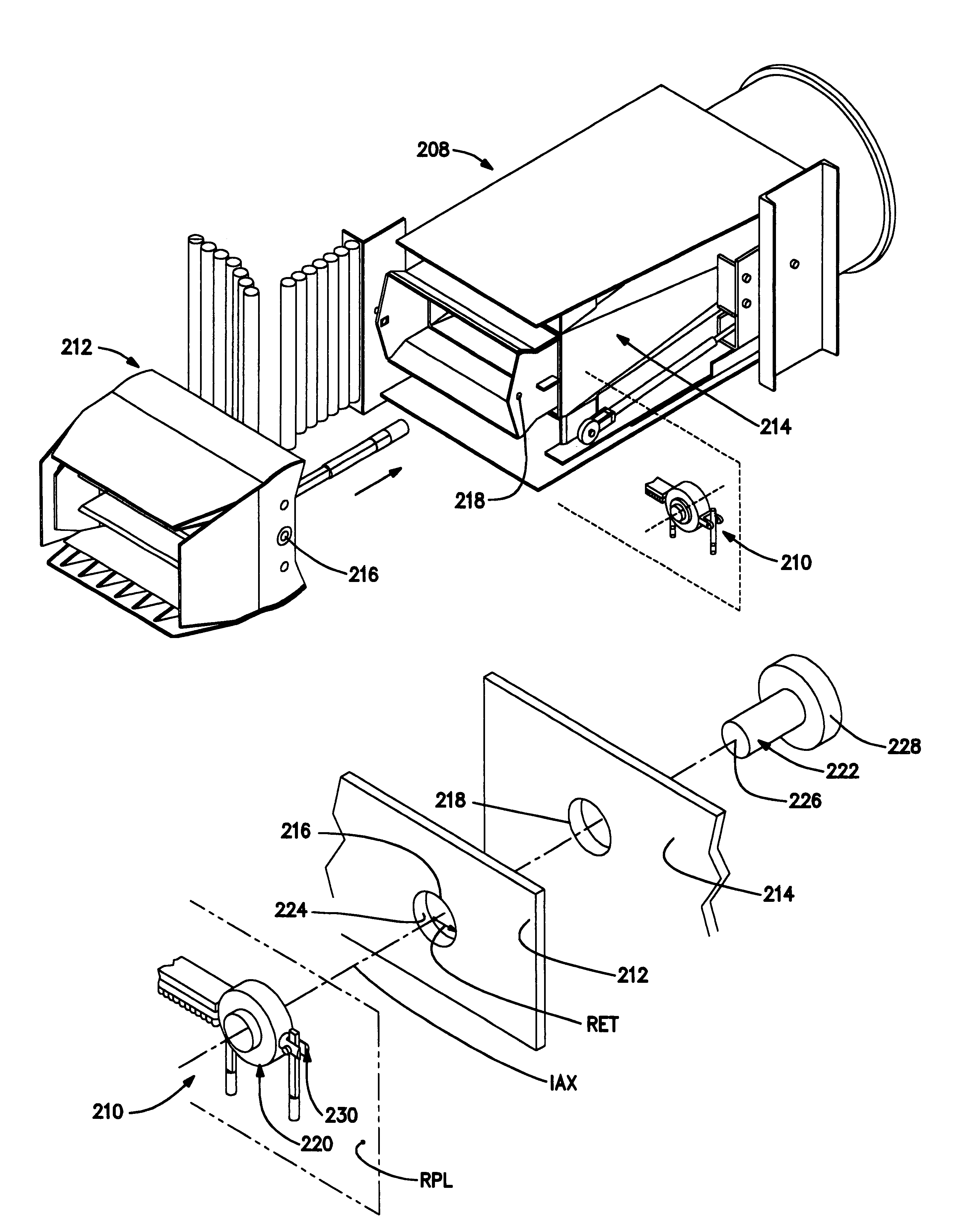
A pivot mounting apparatus 210 is provided for pivotally mounting to one another the coal nozzle tip 212 and coal nozzle body 214 of a pulverized solid fuel nozzle 208 of a pulverized solid fuel-fired furnace 10. The pivot mounting apparatus 210 includes a latch interconnecting assembly 220 that includes a pin 222 for insertion in a traversing movement through an insertion passage 224 which passes through both the through hole 216 of the coal nozzle tip 212 and the through hole 218 of the coal nozzle body 214 upon the mutually facing positioning of respective sides of the coal nozzle tip 212 and the coal nozzle body 214 with one another with their respective through holes 216, 218 both co-axial with an insertion axis IAX.

Description

BACKGROUND OF THE INVENTION[0001]The present invention relates to a fuel nozzle for a fossil fuel fired combustion arrangement of the type having fossil fuel delivery systems that deliver pulverized coal to coal fired steam generators and more specifically, to a pulverized solid fuel nozzle having a pulverized solid nozzle tip pivotally mounted relative to the pulverized solid nozzle body of the pulverized solid fuel nozzle.[0002]It has long been known in the prior art to employ pulverized solid fuel nozzle tips in firing systems of the type that are utilized in pulverized solid fuel-fired furnaces. U.S. Pat. No. 2,895,435 discloses a tilting nozzle designed to provide substantially uniform distribution of the fuel-air mixture leaving the tilting nozzle and substantially uniform velocity across the discharge opening of the tilting nozzle into the furnace. To this end, the tilting nozzle includes an inner conduit within an outer conduit and a plurality of baffles or division walls wi...

Claims


Application Information

Patent Timeline
Patent Type & Authority Patents(United States)
IPC IPC(8): F23D1/00F23D1/02F23K3/00F23C5/06
CPCF23C5/06F23D1/00
Inventor MANN, JEFFREY SCOTTMULLER, CHRISTOPHER GERALDNOWAK, RONALD HENRY
Owner GENERAL ELECTRIC TECH GMBH
Learn More