
Pigtail fastener

a technology of pigtails and fasteners, which is applied in the direction of hose connections, knotting, fishing, etc., can solve the problems of undesirable wear and tear of prior fastener devices, undesirable and even dangerous, etc., and achieve the effect of increasing the holding power and enhancing the ability of the retaining structure to hold the lin

Inactive Publication Date: 2005-11-01
PIGTAIL FASTENER
View PDF48 Cites 8 Cited by
  • Summary
  • Abstract
  • Description
  • Claims
  • Application Information

AI Technical Summary

Benefits of technology

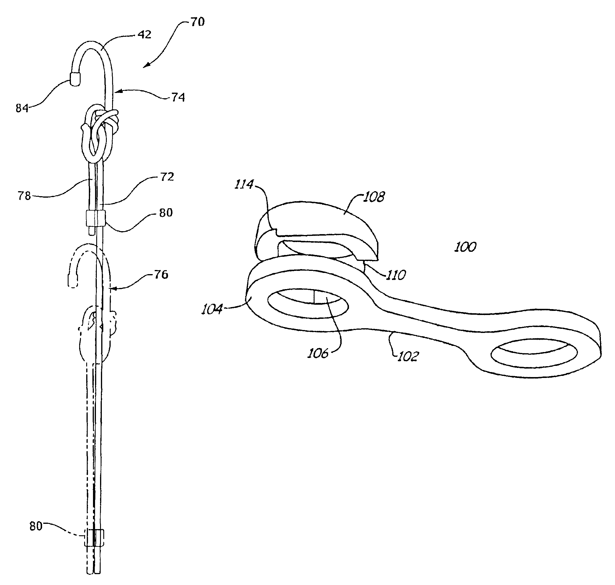
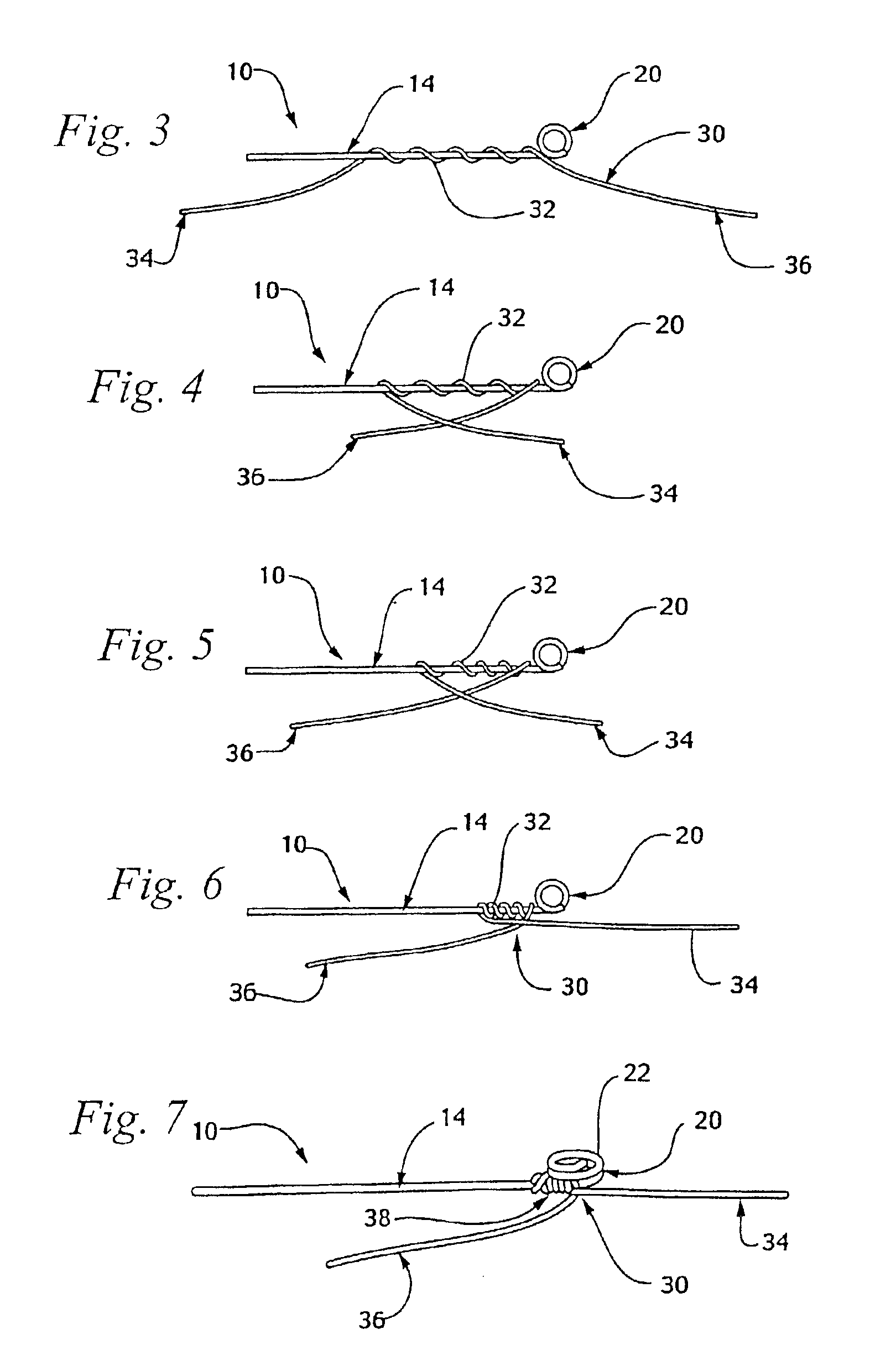
[0006]In one embodiment, the present invention provides a shaft and at least one end of the shaft is shaped into an insertion structure. The configuration of the shaft and the insertion structure directs a line through a particular fastened path, facilitating the securing of the line in a manner such that one can apply frictional force so the knot does not unravel or untie. Conversely, the configuration of the shaft and the insertion structure facilitates an unfastened path, allowing quick and easy removal of the line from the device.
[0008]The retaining structure may be embodied in a variety of forms and each form may have several features. Some features of the retaining structure may include a flattened portion, notches, bows, protruding lips and changing diameters. These features enhance the retaining structure's ability to hold the line. One embodiment of the retaining structure is a coil. The coil may consist of a lower coil and an upper coil offset from the lower coil. The offsetting of the coils provides increased holding power in the retaining structure. Another embodiment of the retaining structure is an arc. Yet another embodiment of the retaining structure is a 2-prong configuration.

Problems solved by technology

Further, the nature and function of most fastener devices require that any knot formed between the fastener and the line be permanent, thus necessitating a cutting of the line to remove the fastener from the line.
In addition to the damage associated with cutting the line, prior fastener devices may place undesirable wear and tear on a line.
Finally, many known fasteners allow line to slip or loosen which can be undesirable and even dangerous.

Method used


Image

  • Pigtail fastener
  • Pigtail fastener
  • Pigtail fastener

Examples


Embodiment Construction

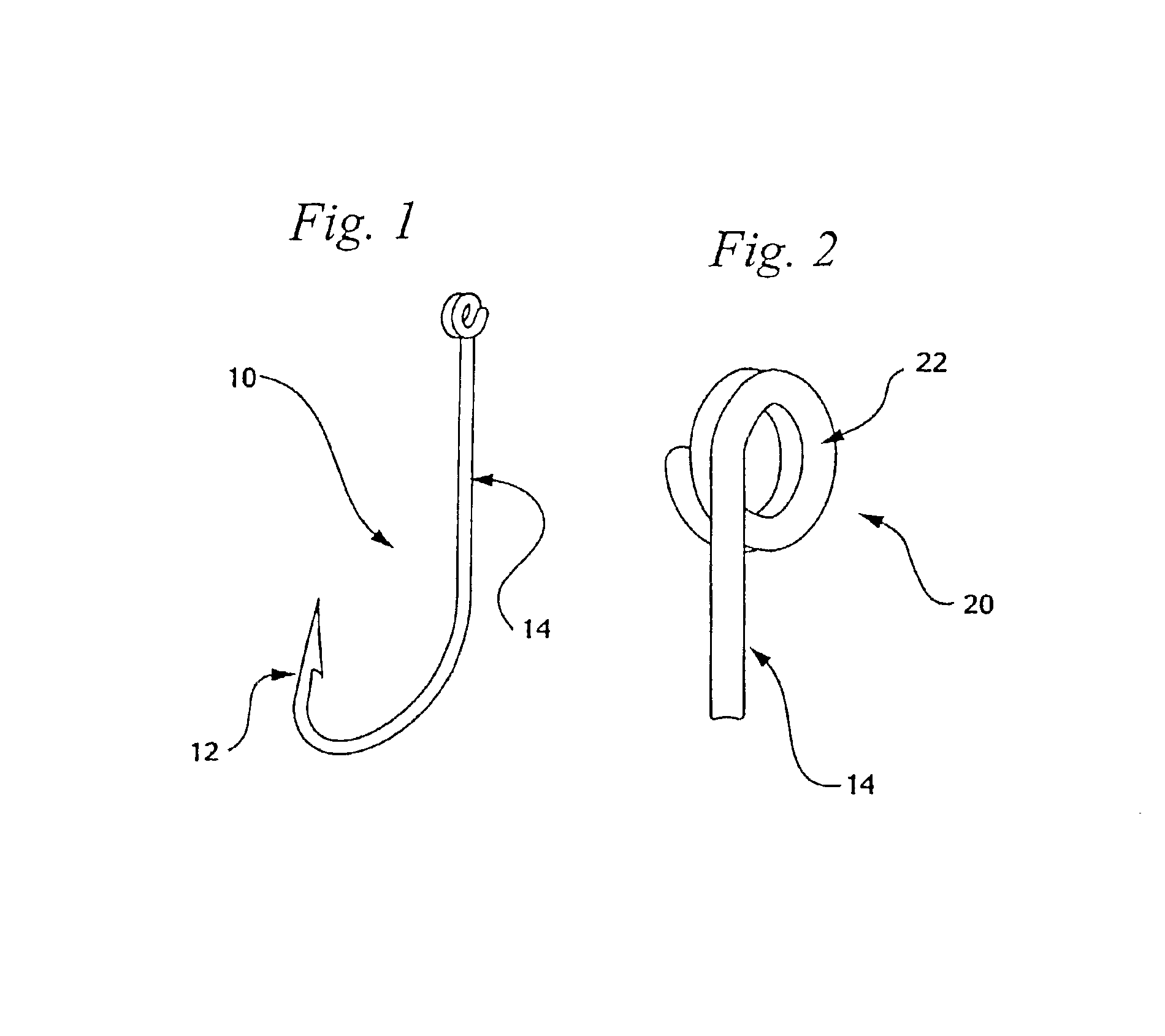
[0035]The inventive aspect of the present pigtail fastener focuses upon a unique coiled region located at the distal end of an elongate shaft that is constructed to pinch and secure a line therein. As shown in the various figures, the pigtail fastener is preferably a coiled shaft portion of a metal implement. However, it should be noted that an implement could be retrofitted to include a pigtail fastener. The pigtail fastener is preferably constructed from a metal such as spring steel that has been tightly coiled and is immediately proximate to the shaft.

[0036]FIG. 1 shows the present pigtail fastener as incorporated into a fishhook embodiment. The fishhook 10 has a hook or barbed portion 12, a shaft 14 and a pigtail fastener 20. As better seen in FIG. 2 the preferred embodiment of the pigtail fastener 20 includes a shaft 14 that has been configured into a coil 22. The terms coil or coiled portion herein defines an extension of the shaft that has been shaped or molded or otherwise f...


PUM


Abstract

An apparatus for releasably securing a line having a cross sectional thickness and at least one free end. The fastener has a shaft dimensioned for wrapping the line around the shaft. The shaft has a pair of ends at least one of which includes: an insertion structure extending from the end that defines an insertion opening and a retaining structure extending from the end a distance greater than the cross sectional thickness of the line. The retaining structure defines a retention aperture operably dimensioned smaller than the cross sectional thickness of the line. When the free end of the line is inserted through the opening, positioned adjacent the shaft, wrapped around the shaft and positioned in the retention aperture, the line is thereby releasably secured.

Description

RELATED APPLICATIONS[0001]This application is a continuation-in-part of application Ser. No. 09 / 378,320 filed Aug. 20, 1999 now U.S. Pat. No. 6,434,799.FIELD OF THE INVENTION[0002]This invention relates generally to a device for gripping and holding cord, rope, wire or other line. More particularly, the present invention is a fastener device that has a unique retaining structure constructed by shaping the end or ends of a shaft into various configurations that facilitate securing the line.BACKGROUND OF THE INVENTION[0003]Previous line fastener devices typically required a degree of fine motor skills and manual dexterity to quickly and properly thread and knot the line to the fastener. Prior fastener devices also require the use of both hands to properly thread and tie the line to the fastener. Further, the nature and function of most fastener devices require that any knot formed between the fastener and the line be permanent, thus necessitating a cutting of the line to remove the fa...

Claims


Application Information

Patent Timeline
IPC IPC(8): A01K83/00A01K91/047A01K91/00D04G5/00F16G11/00F16G11/14
CPCA01K83/00A01K91/047F16G11/00F16G11/14Y10S24/908Y10T24/3991Y10T24/392Y10T24/3918Y10T24/1404Y10T24/3998Y10T24/3916F16G11/046
Inventor KUSLICH, STEPHEN D.PETERSON, FRANCIS
Owner PIGTAIL FASTENER
Learn More