
Diagnosis and repair system and method

a technology applied in the field of diagnostic and repair system and method, can solve the problems of inability to identify, increase the amount of paper needed to describe the machine to assist with the repair process, and difficult to diagnose, so as to reduce the number of locomotive failures, and achieve significant productivity gains and cost savings for the railroad

Inactive Publication Date: 2005-10-25
GE GLOBAL SOURCING LLC
View PDF69 Cites 208 Cited by
  • Summary
  • Abstract
  • Description
  • Claims
  • Application Information

AI Technical Summary

Benefits of technology

This system reduces locomotive failures, minimizes downtime, and provides significant productivity gains and cost savings by enabling accurate and efficient diagnosis and repair, leveraging expert recommendations and real-time data analysis for predictive maintenance.

Problems solved by technology

The diagnosis, maintenance, and repair of a complex vehicle, such as an off-road vehicle, ship, airplane or railroad locomotive involves extremely complex and time consuming processes.
However, if the problem is complex and the root cause difficult to discern, the experienced technician may be unable to identify the problem and certainly much less likely to prognosticate problems before they occur.
It is obvious that as the complexity of the machine increases, the amount of paper needed to describe the machine to assist with the repair process likewise increases.
Yet another problem with a paper-based system is the variety of fielded configurations, each having its own unique technical support documentation.
Adding this configuration complexity to a paper-based system presents an inordinately complex and unmanageable problem of locating the correct technical repair documentation for a specific locomotive.
Another repair issue involving complex machines, such as railroad locomotives or other mobile assets, is the unavailability of a repair history from which one could predict component failures and undertake preventative maintenance beforehand.
Although such a device represents an improvement over a paper-based system, it falls short of the informational needs for a complex machine, such as a locomotive, and fails to advantageously utilize the various technologies available for more efficiently predicting and performing the repair.

Method used


Image

  • Diagnosis and repair system and method
  • Diagnosis and repair system and method
  • Diagnosis and repair system and method

Examples


Embodiment Construction

[0022]Before describing in detail the particular diagnosis and repair system and method in accordance with the present invention, it should be observed that the present invention resides primarily in a novel combination of processing steps and hardware related to the diagnosis and repair process for a locomotive. Accordingly, these processing steps and hardware components have been represented by conventional processes and elements in the drawings, showing only those specific details that are pertinent to the present invention, so as not to obscure the disclosure with structural details that will be readily apparent to those skilled in the art having the benefit of the description herein.

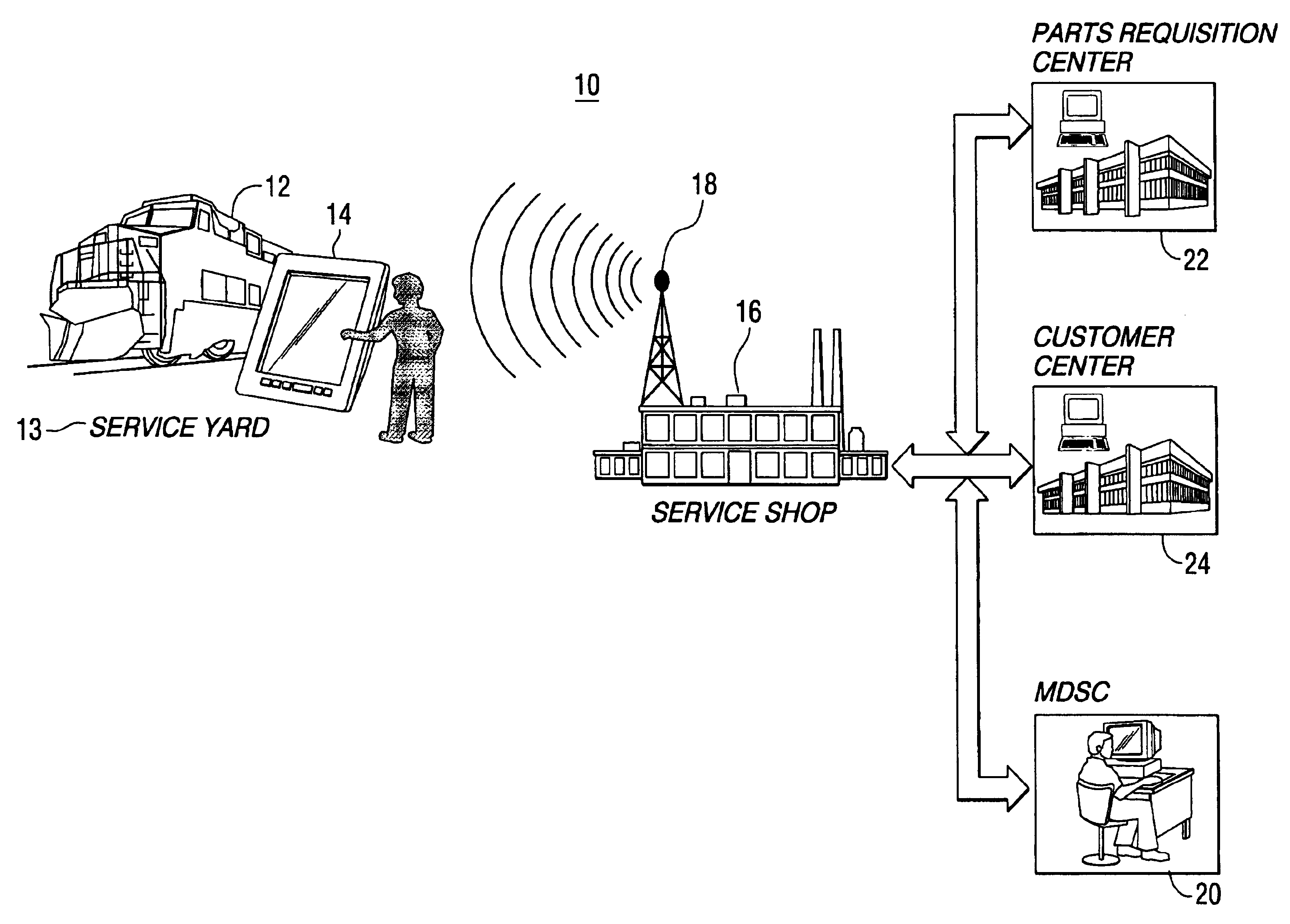
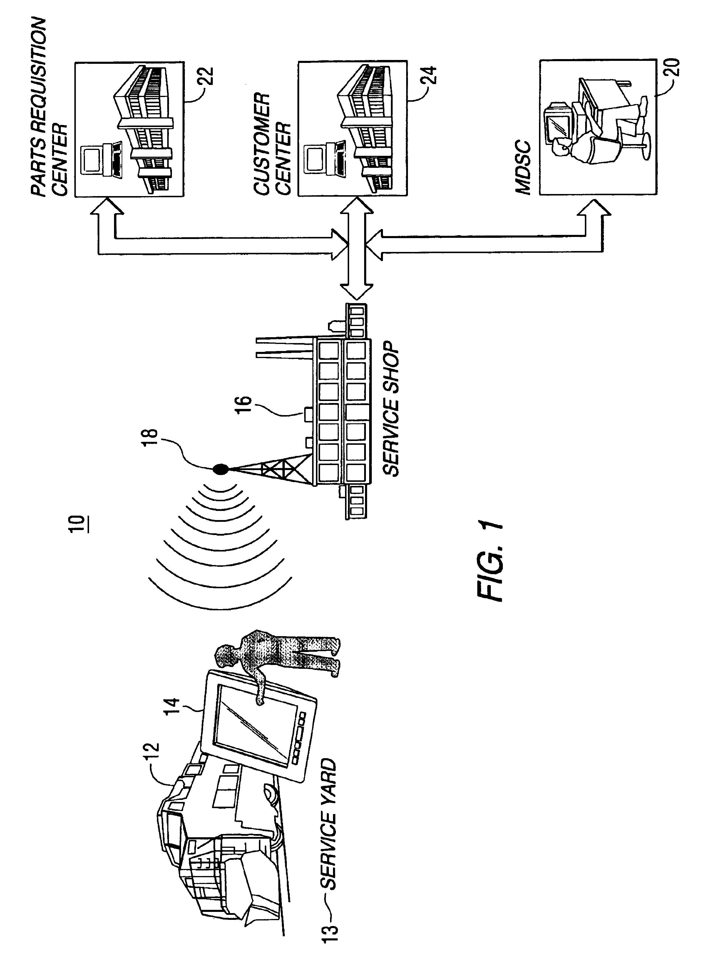
[0023]FIG. 1 is a pictorial rendering of a diagnosis and repair system embodying the inventive aspects of the present invention. Although illustrated and described with respect to a railroad locomotive 12, the teachings of the present invention may be applied to other types of mobile assets especial...


PUM


Abstract

A diagnosis and repair recommendation system for a railroad locomotive is disclosed. The system uses generalized repair recommendations and instantiates them to a specific repair process for a unique road number locomotive. In addition to repair steps to be executed by the technician, the method and system remotely provides supporting documentation specifically tailored for each step in the repair process. As the repair is being conducted, feedback information is entered by the technician. The repair recommendations and the supporting documents are available to the technician via a remote unit, thereby allowing the technician to access the repair steps and supporting documentation while the repair is in progress.

Description

[0001]This application claims the benefit of U.S. Provisional Application 60 / 162,046 filed on Oct. 28, 1999 and U.S. Provisional Application 60 / 225,331 filed on Aug. 14, 2000.BACKGROUND OF THE INVENTION[0002]This invention relates to a method and system for receiving repair recommendations and related information from a central diagnostic and repair service center at a remote location, for repairing, for instance, a railroad locomotive.[0003]The diagnosis, maintenance, and repair of a complex vehicle, such as an off-road vehicle, ship, airplane or railroad locomotive involves extremely complex and time consuming processes. Efficient and cost-effective operation of a fleet of such vehicles necessitates a reduction in the number of vehicle road failures and minimization of vehicle down-time. This can be accomplished by predicting impending failures, by performing preventative maintenance, and by performing repairs quickly and accurately. For example, it will be appreciated that the ab...

Claims


Application Information

Patent Timeline
Patent Type & Authority Patents(United States)
IPC IPC(8): B61L27/00G06Q10/00G07C5/00
CPCB61L27/0094G06Q10/06G07C5/008B61L27/57
Inventor ABDEL-MALEK, AIMANSCALLAN, BRIANBRUNO, JEANETTE M.MATHEWSON, BRYAN A.SCHLABACH, JAMES E.FERA, GREGORY J.GOMEZ, IVAN
Owner GE GLOBAL SOURCING LLC
Learn More