
Device for programmable frequency divider

a frequency divider and device technology, applied in the field of frequency dividers, can solve the problems of system taking false actions, cycle produced is not necessarily 50, and the process of transporting output to the multiplexer often produces different delays, so as to reduce the possibility of clock glitch signals, save energy, and eliminate the effect of clock glitch signals

Inactive Publication Date: 2005-10-25
ELAN MICROELECTRONICS CORPORATION
View PDF1 Cites 15 Cited by
  • Summary
  • Abstract
  • Description
  • Claims
  • Application Information

AI Technical Summary

Benefits of technology

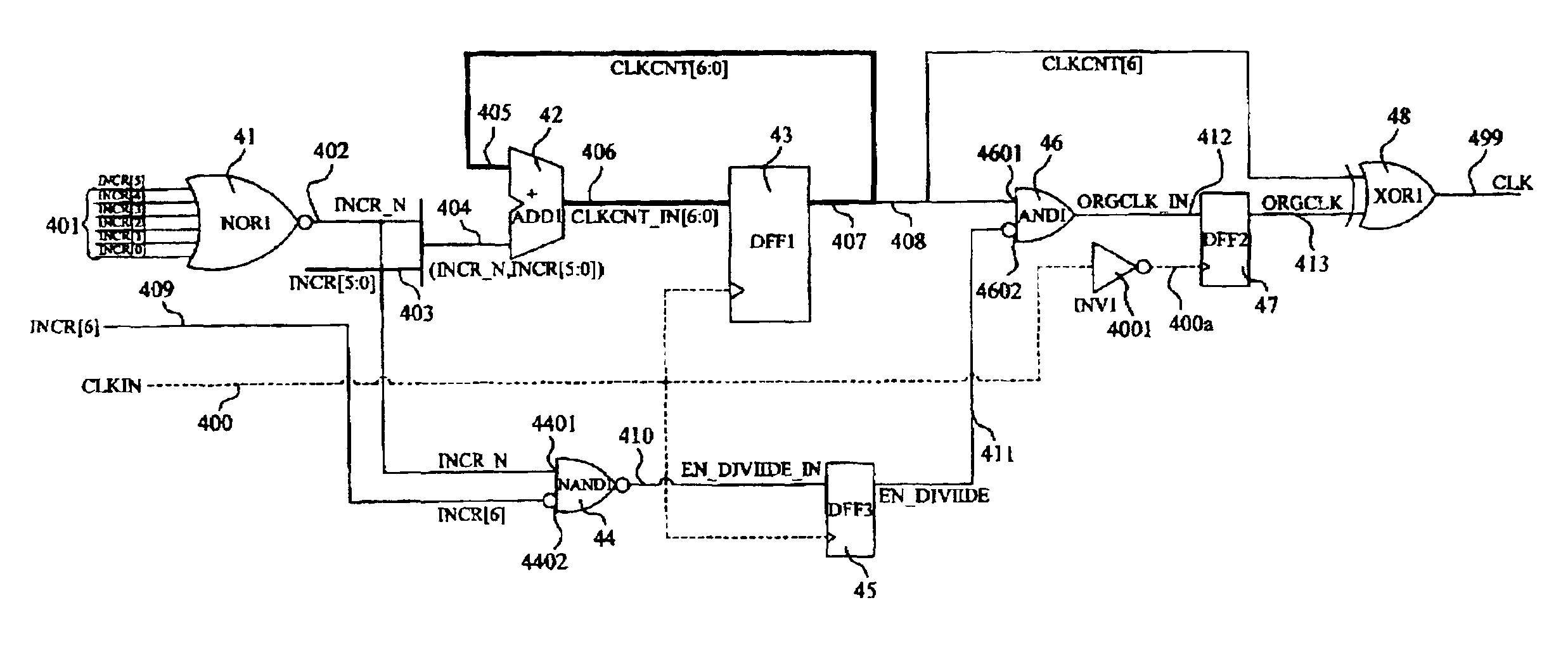
The present invention provides a programmable frequency divider with programmable controls to reach the goal of frequency dividing. It also outputs different multipliers of frequency dividing clock signals from the same output point, without the need for a choice signal of the multiplexer to remove the possibility of a clock glitch signal. This creates a stable, energy saving working condition. The programmable frequency divider does not cause the occurrence of a clock glitch signal. Additionally, it provides a programmable frequency divider for clock with a duty cycle of 50%-50%. The programmable frequency divider comprises one n-bit adder and one n-bit D Flip Flop. The adder takes one adjustment parameter and one return signal as a basis to create one first output signal, while the D Flip Flop and adder create a cycle to receive the first output signal and its given import clock, thus creating the second output signal. The second output signal comprises a return signal and the target signal. The D Flip Flop sends the return signal back to the adder, which will make addition calculations under the given adjustment parameter, finally giving out the target clock with the target signal as a calculation basis.

Problems solved by technology

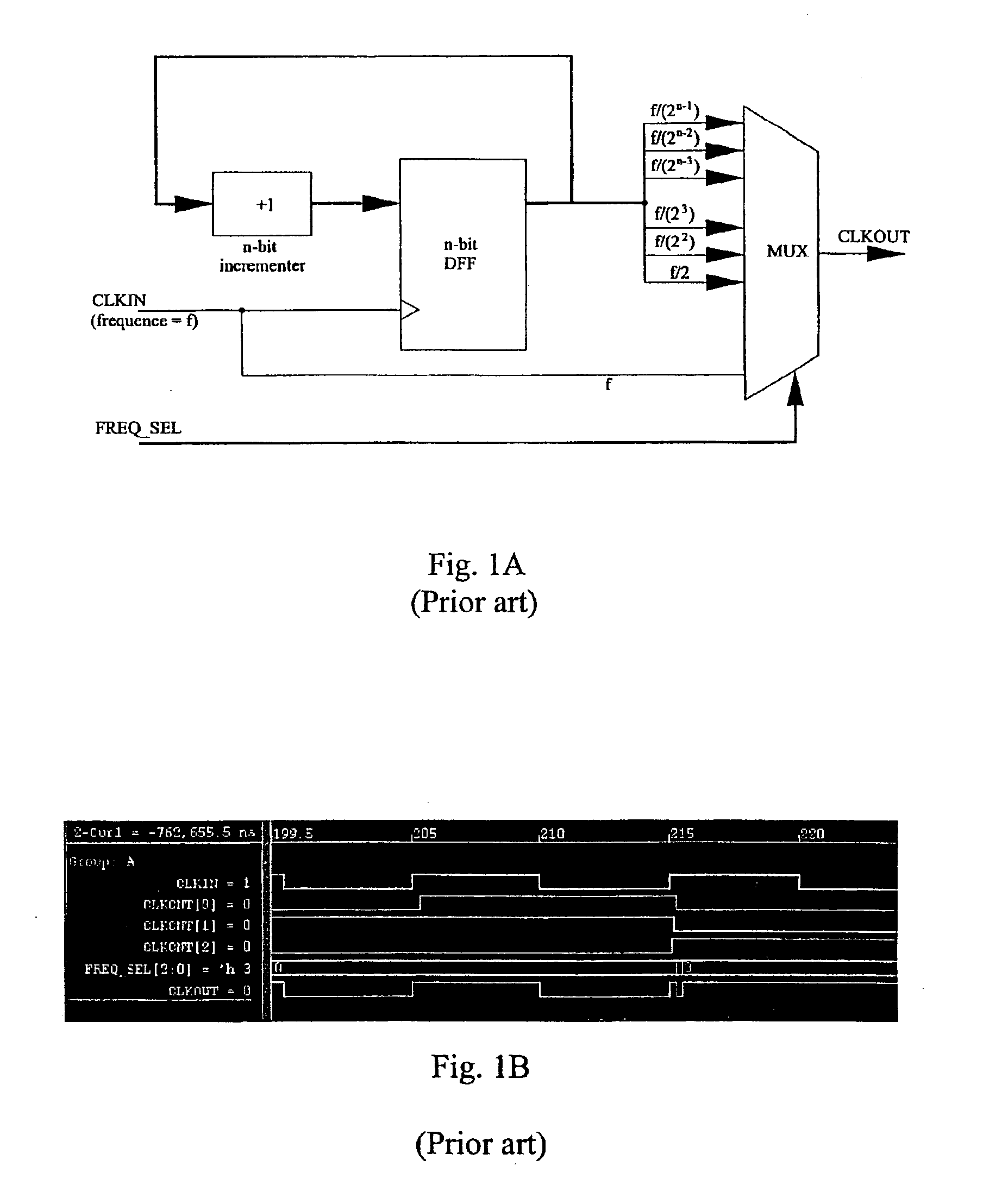
During the layout, the positions of each D Flip Flop are different; therefore the process of transporting output to the multiplexer often produces different delays.
Naturally, over a period of time the signal will eventually change to the target signal, but under certain circumstances, this could have a large impact on the procedures.
Because of this, the system might take false actions.
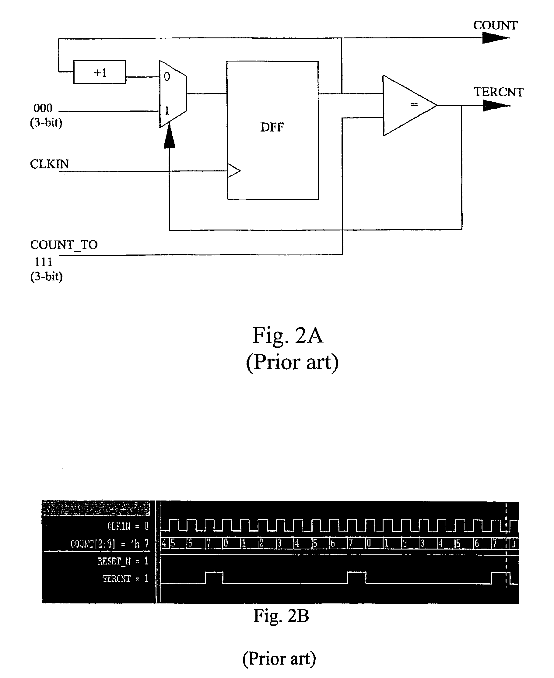
As shown on FIG. 2B, if this pulse signal is used as a clock, it has a disadvantage that the duty cycle produced is not necessarily 50%—50%, furthermore there is the possibility of an occurrence of a glitch signal.

Method used


Image

  • Device for programmable frequency divider
  • Device for programmable frequency divider
  • Device for programmable frequency divider

Examples


Embodiment Construction

[0020]To help the present invention to achieve the above mentioned objectives, all necessary techniques, methods and concrete structural features are described below in a practical example. To further improve the understanding, in the following, the present invention is described in detail with reference to the included pictures.

[0021]The present invention provides a programmable frequency divider, which is used to transform one import clock (an oscillator can be used to create said import clock) to one target clock. The frequency of the said import clock is 2m times of the target clock frequency, with m being an integer larger than zero. Please refer to FIG. 3A, the displayed structure comprising: one n-bit adder 31 and one n-bit D Flip Flop 32. The n-bit D Flip Flop 32 means the inputs of D Flip Flop have n-bits and the clock pulse. One adjustment parameter 301 and one return signal 302 are used together to create one first output signal 303 with the adjustment parameter including...


PUM


Abstract

The present invention relates to a programmable frequency divider having one n-bit adder and one n-bit D Flip Flop. These are used to transform the import clock to the target clock. The adder takes one adjustment parameter and one return signal as a basis to create the first output signal, with the possibility to program the adjustment parameter. The D Flip Flop and the adder create a cycle, which is used to receive the first output signal and its import clock to create the second output signal. The second output signal is separated into a return signal and the target signal. The D Flip Flop sends the return signal back to the adder, which will make addition calculations under the adjustment parameter, finally giving out the target clock with the target signal as a calculation basis.

Description

FIELD OF THE INVENTION[0001]The present invention relates to a frequency divider, in particular to a programmable frequency divider in which an adjustment parameter is controlled by a program command.BACKGROUND OF THE INVENTION[0002]In digital systems with corresponding clock speed rates, a clock signal plays a very important role, besides determining the performance of the system, it is closely related to an electricity usage. Since mobile solutions are popular, most PC CPUs, digital signal processors (DSP) and miniature controlling units have steadily lowered their power consumption to achieve a goal of saving electricity. During times of inactivity of the controlling units, the system is switched to a state of a lower work frequency.[0003]For normal traditional frequency dividing installations, please refer to FIG. 1A. It usually comprises one n-bit D Flip Flop (DFF) together with one adder. This structure gives a different frequency signal after the frequency lowering process, w...

Claims


Application Information

Patent Timeline
Patent Type & Authority Patents(United States)
IPC IPC(8): H03K23/66H03K23/00
CPCH03K23/662
Inventor WANG, JUNG-CHIHHU, CHAO-YU
Owner ELAN MICROELECTRONICS CORPORATION
Learn More