
Systems and methods for performing simultaneous ablation

a technology of simultaneous ablation and tissue, applied in the field of medical devices, can solve the problems of reducing the electrical conductivity of the lesion, limiting the volume of tissue, and limiting so as to increase the size of the lesion created

Active Publication Date: 2005-10-25
BOSTON SCI SCIMED INC
View PDF10 Cites 102 Cited by
  • Summary
  • Abstract
  • Description
  • Claims
  • Application Information

AI Technical Summary

Benefits of technology

The present invention is about systems and methods for delivering energy to tissue to create lesions. The invention provides a system that can deliver energy to multiple electrode arrays simultaneously, which increases the volume of tissue being treated. The system includes a source of energy, two ablation devices with parallel wires, and a ground electrode. The method involves inserting the electrodes into the tissue region and delivering energy to create lesions at the sites. The invention allows for simultaneous treatment of multiple tissues and can be used in the treatment of benign or cancerous tumors.

Problems solved by technology

Due to physical changes within the tissue during the ablation process, the size of the lesion created may be limited.
For example, the concentration of heat adjacent to wires often causes the local tissue to desiccate, thereby reducing its electrical conductivity.
Thus, the rapid fall-off in current density may limit the volume of tissue that can be treated by the wire electrodes.
As such, depending upon the rate of heating and the size of the wire electrodes, existing ablation devices may not be able to create lesions that are relatively large in size.
The effectiveness of such devices, however, may be limited by the desiccation and / or vaporization process discussed previously.
While wire electrodes can be deployed, activated, retracted, and repositioned sequentially to treat multiple locations within a tissue region, such an approach may increase the length of time of a procedure, and precise positioning to ensure that an entire tissue region is treated may be difficult to accomplish.

Method used


Image

  • Systems and methods for performing simultaneous ablation
  • Systems and methods for performing simultaneous ablation
  • Systems and methods for performing simultaneous ablation

Examples


Embodiment Construction

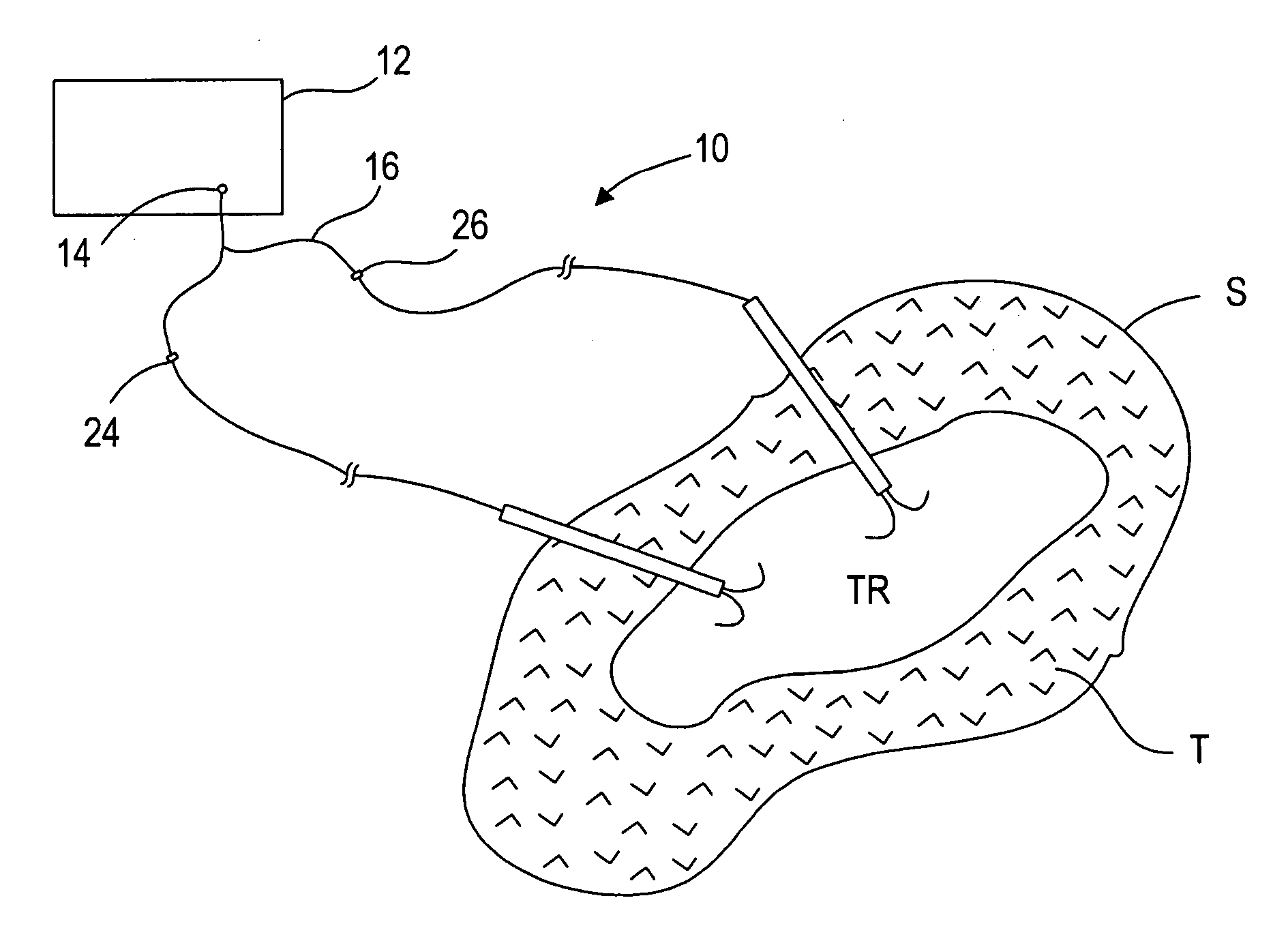
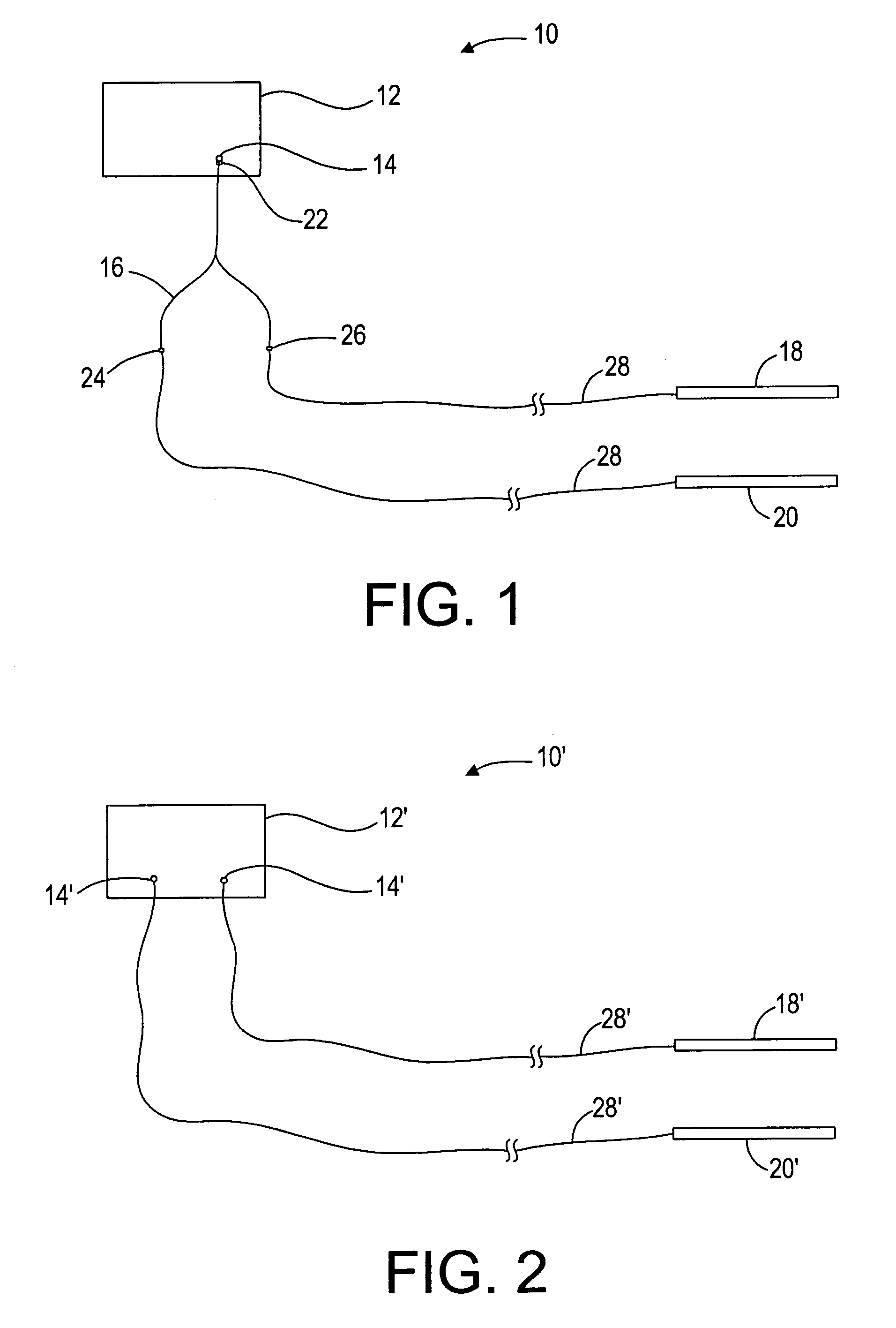
[0025]Referring now to the drawings, in which similar or corresponding parts are identified with the same reference numeral, FIG. 1 shows a preferred embodiment of an ablation system 10, in accordance with the present invention. The ablation system 10 includes a source of energy 12, e.g., a radio frequency (RF) generator, having an output terminal 14, a connector 16, a first ablation device 18, and a second ablation device 20. One or both of the first and the second ablation devices 18, 20 may be capable of being coupled to the generator 12.

[0026]The generator 12 is preferably capable of operating with a fixed or controlled voltage so that power and current diminish as impedance of the tissue being ablated increases. Exemplary generators are described in U.S. Pat. No. 6,080,149, the disclosure of which is expressly incorporated by reference herein. The preferred generator 12 may operate at relatively low fixed voltages, typically below one hundred fifty volts (150 V) peak-to-peak, a...


PUM


Abstract

A system for treating tissue includes first and second ablation devices each including a plurality of wire electrodes and coupled to a generator in parallel. In one embodiment, the generator includes first and second terminals coupled in parallel to one another, and the first and second ablation devices are connected to the first and second terminals, respectively. Alternatively, the first and second ablation devices are coupled to a single terminal of the generator using a “Y” cable. A ground electrode is coupled to the generator opposite the first and second ablation devices for monopolar operation. The first and second arrays of electrodes are inserted into first and second sites adjacent one another within a tissue region. Energy is simultaneously delivered to the first and second arrays to generate lesions at the first and second sites preferably such that the first and second lesions overlap.

Description

BACKGROUND OF THE INVENTION[0001]1. Field of the Invention[0002]The field of the invention relates to medical devices, and more particularly, to systems and methods for ablating or otherwise treating tissue using electrical energy.[0003]2. Background of the Invention[0004]Tissue may be destroyed, ablated, or otherwise treated using thermal energy during various therapeutic procedures. Many forms of thermal energy may be imparted to tissue, such as radio frequency electrical energy, microwave electromagnetic energy, laser energy, acoustic energy, or thermal conduction.[0005]In particular, radio frequency ablation (RFA) may be used to treat patients with tissue anomalies, such as liver anomalies and many primary cancers, such as cancers of the stomach, bowel, pancreas, kidney and lung. RFA treatment involves the destroying undesirable cells by generating heat through agitation caused by the application of alternating electrical current (radio frequency energy) through the tissue.[0006...

Claims


Application Information

Patent Timeline
Patent Type & Authority Patents(United States)
IPC IPC(8): A61B18/14
CPCA61B18/148A61B18/1206A61B2018/00702A61B2018/00875A61B2018/143A61B2018/1475
Inventor RIOUX, ROBERT F.GARABEDIAN, ROBERTJARRARD, JERRY
Owner BOSTON SCI SCIMED INC
Learn More