Toothbrush head with anchor-free bristle tufting

Inactive Publication Date: 2005-10-25
BRAUN GMBH
View PDF33 Cites 87 Cited by
  • Summary
  • Abstract
  • Description
  • Claims
  • Application Information

AI Technical Summary

Benefits of technology

[0008]It is therefore an object of the present invention to provide an improved brush head of the type initially referred to, which eliminates the disadvantages of the prior art and advances it in advantageous manner. In particular it is intended to improve the anchor-free fastening of the tufts, thus eliminating the previously mentioned disadvantages.
[0009]According to the invention the brush head has at least one hole in the bristle carrier, which is divided by means of at least one transverse wall into several segments, the at least one transverse wall being constructed such that the bristles seated in the segments form a common tuft with a smooth and closed outer contour corresponding to the contour of the hole. In other words, seated in the hole is a tuft, which or whose fastening in the hole is divided into several segments but still outwardly forms a uniform tuft field. The transverse wall forms a support wall in the interior of the hole, upon which the bristles of a tuft can take support as well as on the peripheral wall of the hole, particularly to prevent bending. More specifically, this also provides support for those bristles that do not lie around the outer periphery of the hole, making the tuft in question stiffer on the whole. The transverse or support wall reduces the effectively available bending length of the bristles because they can no longer bend freely down to their ends seated in the hole, including the part received in the hole, but are again supported against bending at a point above their ends seated in the holes. The respective tuft thus acquires greater stiffness (the stiffness of a bristle being roughly proportional to its diameter to the power of four divided by the free length of the bristle to the power of three) and the movability of the bristles is reduced, with the result that the user of the brush perceives a greater stiffness of the brush head and cleans accordingly with less force. Bristle wear is reduced and the efficiency of the cleaning operation is improved because the previously described advantages no longer arise. In addition to this it is possible to create, for example, a clear-cut border between variously colored filaments of a tuft by dividing the hole into several segments.
[0010]A further important positive effect of the use of such support walls for tufts fastened to the bristle carrier by the anchor-free tufting method is that the tufts acquire comparable characteristics, in particular comparable stiffness, to those tufts fastened by the anchor tufting method, with the result that their clinical test results are also well comparable. Valuable findings can be drawn and applied from this, and the time and cost for developing the brushes and for conducting separate series of clinical tests can be saved.
[0015]To prevent a gap forming between the segments of a tuft added provision can be made for the at least one transverse wall to taper in thickness toward its upper side, in particular for it to be conically shaped. Opposing sides of the transverse wall are upwardly inclined in V-shape, with the result that the bristles converge, forming a closed, dense tuft without any gaps. Such a construction of the support or transverse wall also makes it easier to insert the bristles in the corresponding hole.
[0016]Provision can also be made for the upper edge of the transverse wall to be rounded off so that the bristles take a harmonious course on the one hand and bristle wear against the upper edge of the transverse wall is prevented on the other hand. Semi-elliptical cross sections and similarly rounded forms of the support wall are possible.

Problems solved by technology

Consequently, a relatively wide gap remains between the individual tufts inserted in the hole subsections with the result that, on the one hand, the tufts located in the complete hole cross section do not form a homogeneous field of bristles and, on the other hand, the stability of the individual bristles is reduced because they are no longer able to lend each other mutual support on account of the presence of the relatively thick plastic partition walls and the attendant gap formation.
One problem concerns the service life of such brushes.
Premature wear occurs as the result of a relatively severe movement of the bristles, particularly in the case of tufts with a non-circular outer contour.
Movability also has an adverse effect on dental cleaning efficiency and reduces the subjectively perceived stiffness of the brush head.
Where electric toothbrushes are concerned, this can reduce the angle of oscillation of the brush head on account of play in the toothbrush gearing, thus impairing cleaning performance.
With the anchor-free tufting method there is a risk of the bristles within a tuft being pushed over each other, making it impossible to perceive a clear-cut, colored border between color-segregated areas of tufts.

Method used


Image

  • Toothbrush head with anchor-free bristle tufting
  • Toothbrush head with anchor-free bristle tufting
  • Toothbrush head with anchor-free bristle tufting

Examples


Embodiment Construction

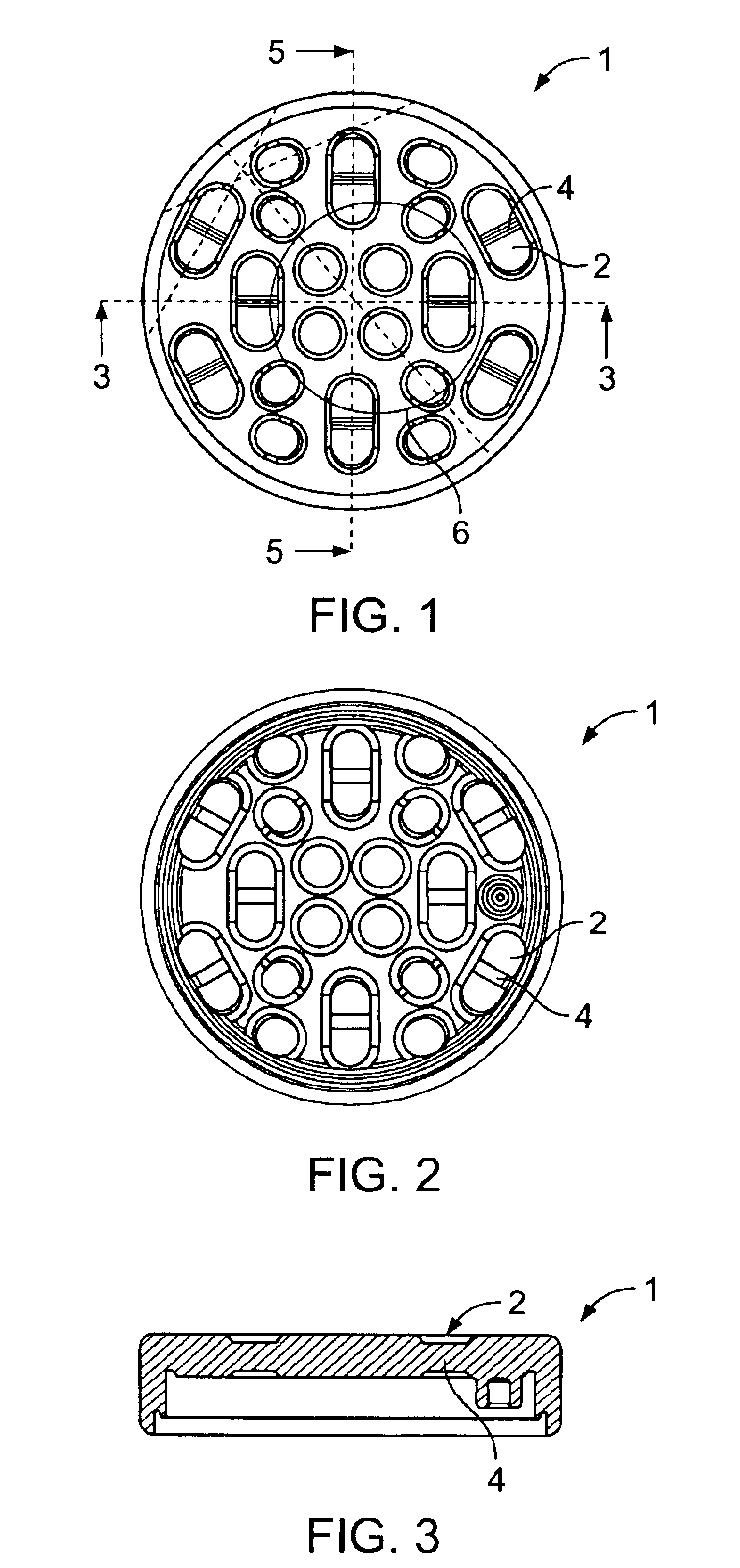
[0038]FIGS. 1 to 3 show the bristle carrier 1, which is essentially constructed as a plane disk with peripheral edges projecting downward which are designed to be secured to the bottom part of a toothbrush head of an electric toothbrush in a snap-fit arrangement or by welding in a manner known in the art. The bristle carrier 1 has a multiplicity of through-holes 2, part of which is of an essentially circular configuration. The balance of the through-holes is constructed as elongate holes (cf. FIG. 1 and FIG. 2). The entire bristle carrier 1 is manufactured as a plastic injection-molded part. The through-holes 2 can be formed simultaneously with the injection-molding operation.

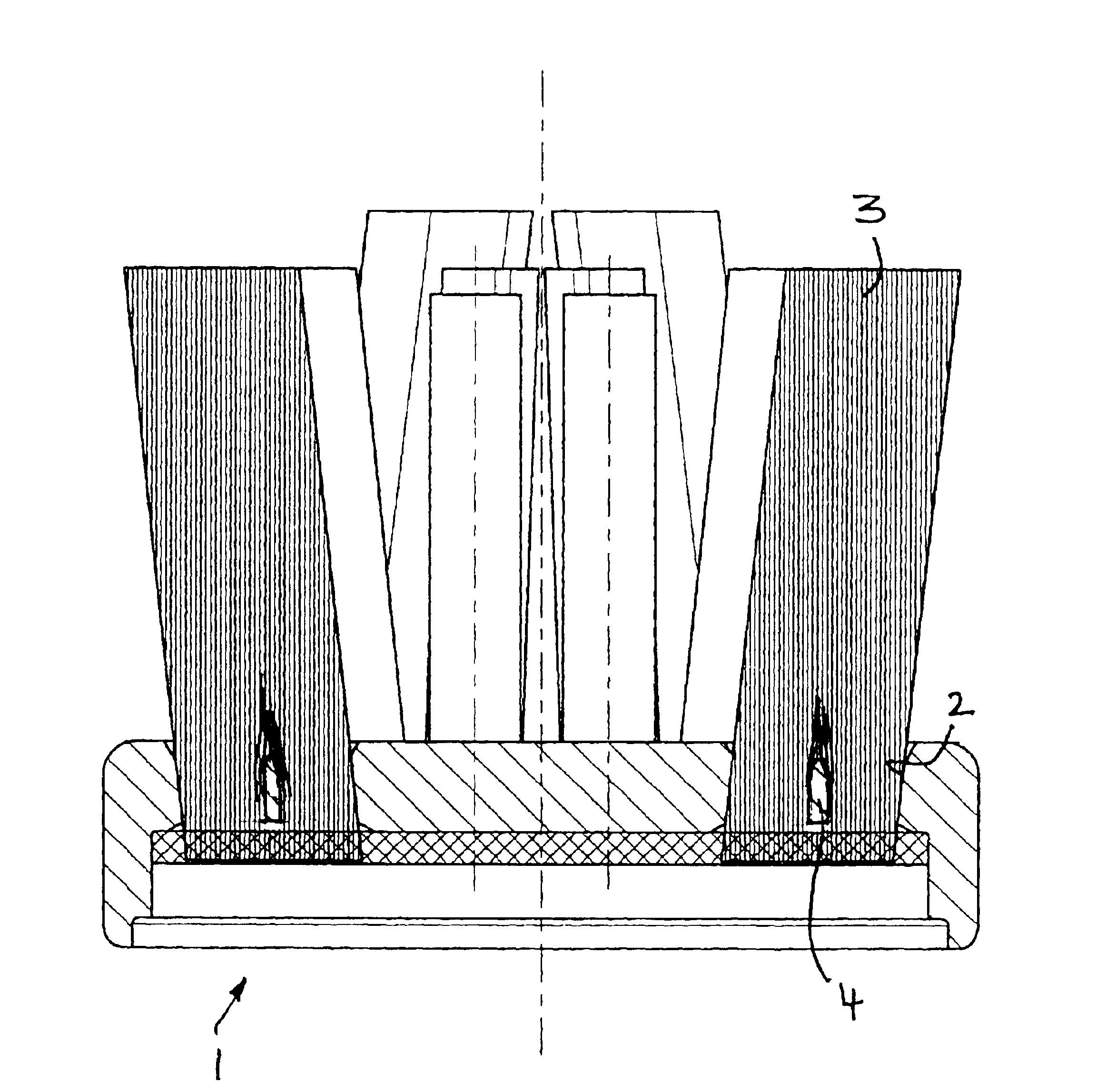
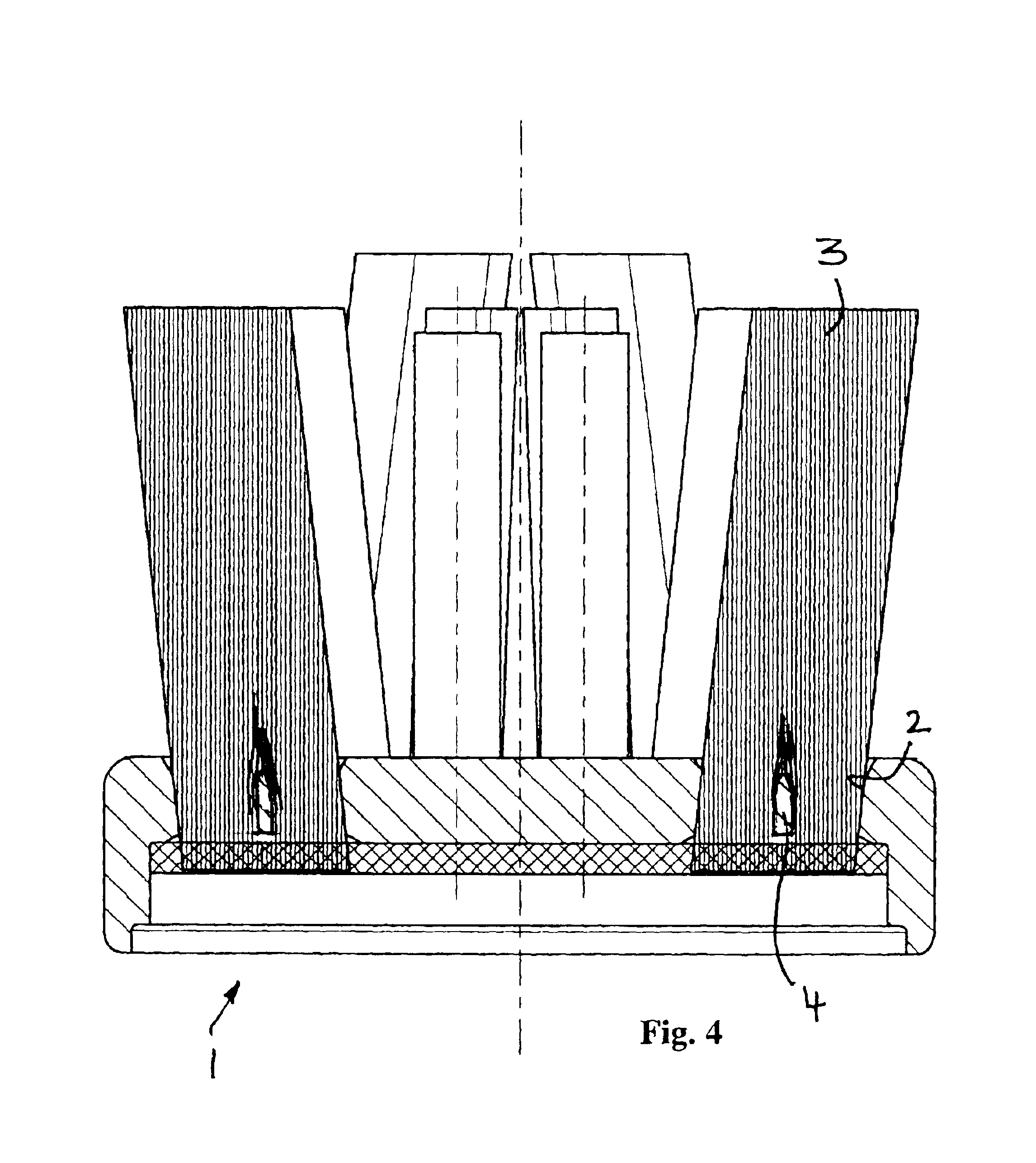
[0039]As is shown in FIG. 4, a multiplicity of bristles is arranged in the holes 2 in the bristle carrier 1 so that they are seated in the holes 2 in the form of tufts 3. Each hole 2 receives one tuft 3 which, as FIG. 4 shows, can be arranged at different angles of tilt. The tufts 3 also have different outer co...


PUM


Abstract

The invention is directed to a brush head, in particular a toothbrush head, having a bristle carrier and bristles attached thereto, which are seated in the form of tufts in holes in the bristle carrier and fastened by their ends close to the bristle carrier to the bristle carrier without anchoring, in particular by welding and / or adhesive bonding to a rear side of the bristle carrier using the method referred to as anchor-free tufting. According to the invention, at least one hole (2) in the bristle carrier (1) is divided by means of at least one transverse wall (4) into several segments and said at least one transverse wall is constructed such that the bristles seated in the segments form a common tuft (3) with a smooth and closed outer contour corresponding to the contour of the hole and are supported by the transverse wall.

Description

TECHNICAL FIELD[0001]This invention relates to a brush head, in particular a toothbrush head, having a bristle carrier and bristles attached thereto, which are seated in the form of tufts in holes in the bristle carrier and fastened by their ends close to the bristle carrier to the bristle carrier without anchoring, in particular by welding and / or adhesive bonding to a rear side of the bristle carrier.BACKGROUND[0002]Unlike the method referred to as anchor tufting which includes arranging the tufts in a U-shaped configuration and, with the aid of small metal anchor plates placed between the legs of the U-shaped tufts, inserting them into a blind-end bore in the bristle carrier where they are fastened by shooting the anchor plate into opposite side walls of the blind-end bore, the bristles are not arranged in U shape in the anchor-free tufting method. In the method referred to as anchor-free tufting the bristles are seated with their one ends in the holes in the bristle carrier while...

Claims


Application Information

Patent Timeline
IPC IPC(8): A46B3/00A46B3/08A46B9/04A46D3/00
CPCA46B3/08A61C17/222A46B2200/1066
Inventor DRIESEN, GEORGESFRITSCH, THOMAS
Owner BRAUN GMBH
Why Eureka
Try Eureka