
Loudspeakers

Inactive Publication Date: 2005-10-18
GOOGLE LLC
View PDF11 Cites 30 Cited by
  • Summary
  • Abstract
  • Description
  • Claims
  • Application Information

AI Technical Summary

Benefits of technology

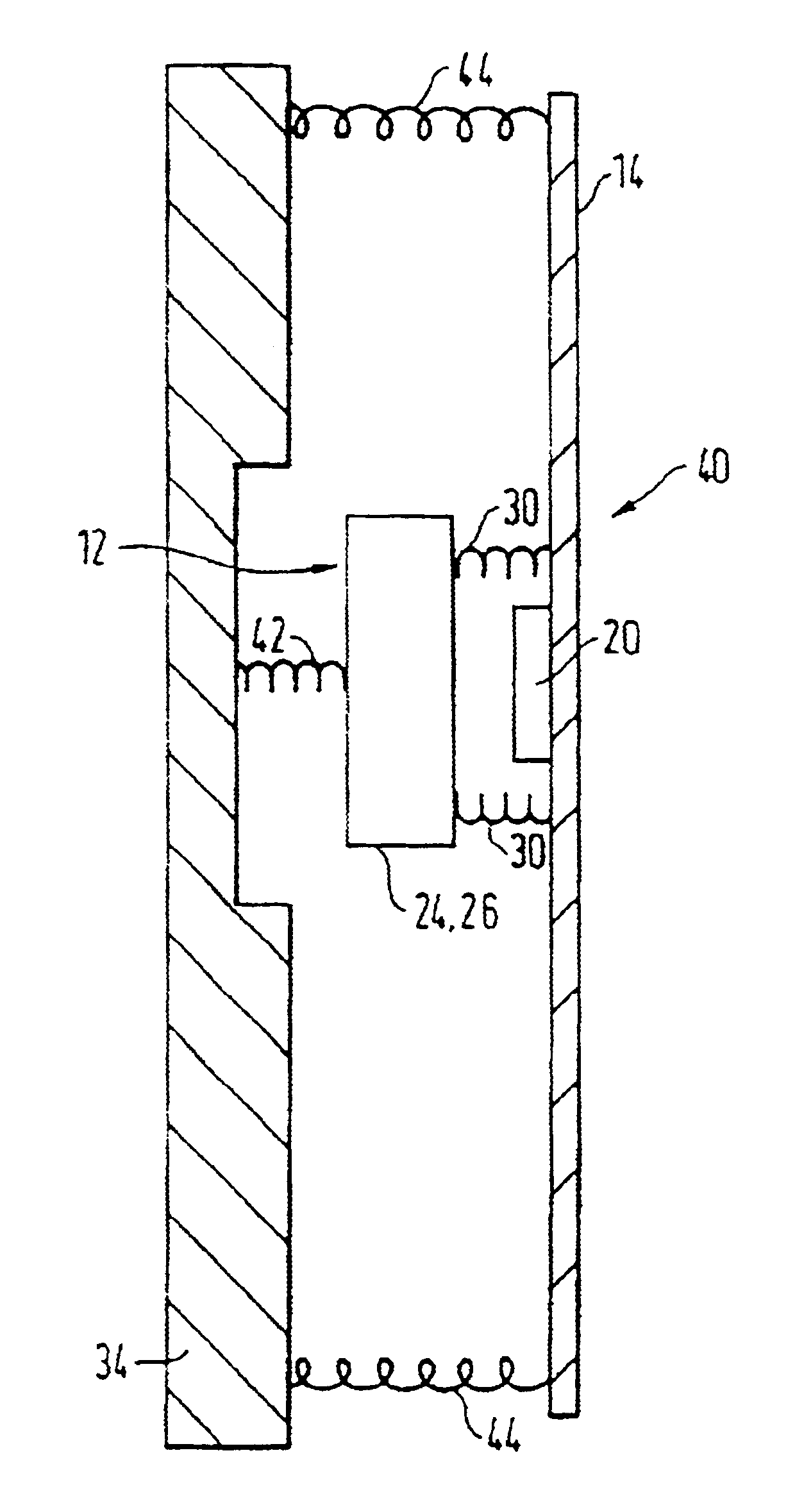
[0008]Coupling the exciter magnet assembly to a frame or the like support confers the advantage of increasing reliability and robustness while providing a resilient coupling can reduce the level of energy imparted to the support. The panel itself may be a fairly lightweight structure, whilst the exciter may be much heavier than the panel particularly in the case of an electrodynamic device.
[0010]The resilient coupling of the exciter to the support may reduce the tendency for the support and drive means to move with the same velocities, and may even obviate coincidence of velocities altogether. Thus, in operation, the panel may not be moving with either the same amplitude or even the same phase as the support. Furthermore, the choice of resilient coupling offers the designer freedom to “tune” resonant panel-form loudspeakers in a manner analogous to optimising multi-cavity and multi-vent loudspeaker systems.
[0012]With median compliance values for the resilient element the higher frequency components of velocity present in the exciter are beneficially more weakly coupled to the support frame and this may reduce the stray acoustic output which the support frame may radiate.
[0019]The support body may take the place of a chassis or basket in a conventional loudspeaker drive unit, although in the present invention the support body is usually not required to be of the same degree of weight and rigidity as is required with a conventional pistonic drive unit. The support body (hereinafter support or support frame) may be a lightweight frame-like structure.

Problems solved by technology

During rough handling or shipping it is possible for the exciter to move undesirably and even cause the pole pieces to contact with the windings of the voice coil, with obvious disastrous results.

Method used


Image

  • Loudspeakers
  • Loudspeakers
  • Loudspeakers

Examples


second embodiment

[0039]FIG. 6 discloses resonant panel loudspeaker (50) embodying a resonant panel member (14) generally as disclosed in International patent application WO97 / 09842 of New Transducers Limited and U.S. counterpart No. 08 / 707,012.

[0040]The loudspeaker (50) comprises a base (52) supporting a generally vertical rectangular light frame (34) which surrounds an acoustic radiator in the form of a stiff lightweight resonant panel (14) which is resiliently suspended in the frame on resilient members, such as rubber-like suspension members, not shown.

[0041]An inertial vibration exciter (12) is mounted to the panel to apply bending waves to the panel to cause it to resonate and the exciter is resiliently coupled to the rectangular frame (34) by means of slender resiliently flexible arms (54) which extend between the rectangular frame and the exciter. The arms (54) may, for example, be moulded integrally with the frame (34). Thus the exciter is located and coupled to the frame against movement in...

third embodiment

[0042]FIGS. 7 to 13 illustrate the present invention in the form of a flat generally rectangular modular loudspeaker drive unit assembly (60) comprising a generally rectangular stiff lightweight resonant acoustic radiator panel (14), e.g. of the kind described in International patent application WO97 / 09842 and U.S. Pat. No. 08 / 707,012 mounted in a surrounding frame or basket (62) with a pair of vibration exciters (12) mounted on the panel (14) to launch bending waves into the panel (14) to cause it to resonate to provide an acoustic output.

[0043]The basket (62) is generally rectangular and snugly encloses the radiator panel (14). The basket has a flat perforate base (66) having a surrounding peripheral lip (68) terminated by outwardly projecting flanges (70) which define a surrounding outwardly facing conduit (64) in which services such as electrical input leads to the vibration exciters (12) can be located. The conduit (64) is thus in the form of a channel extending round the perip...


PUM


Abstract

A loudspeaker drive unit comprising a resonant acoustic radiator, an exciter on the radiator to apply bending wave energy to the radiator to cause it to resonate, a support for the loudspeaker drive unit, and means resiliently coupling the exciter to the support.

Description

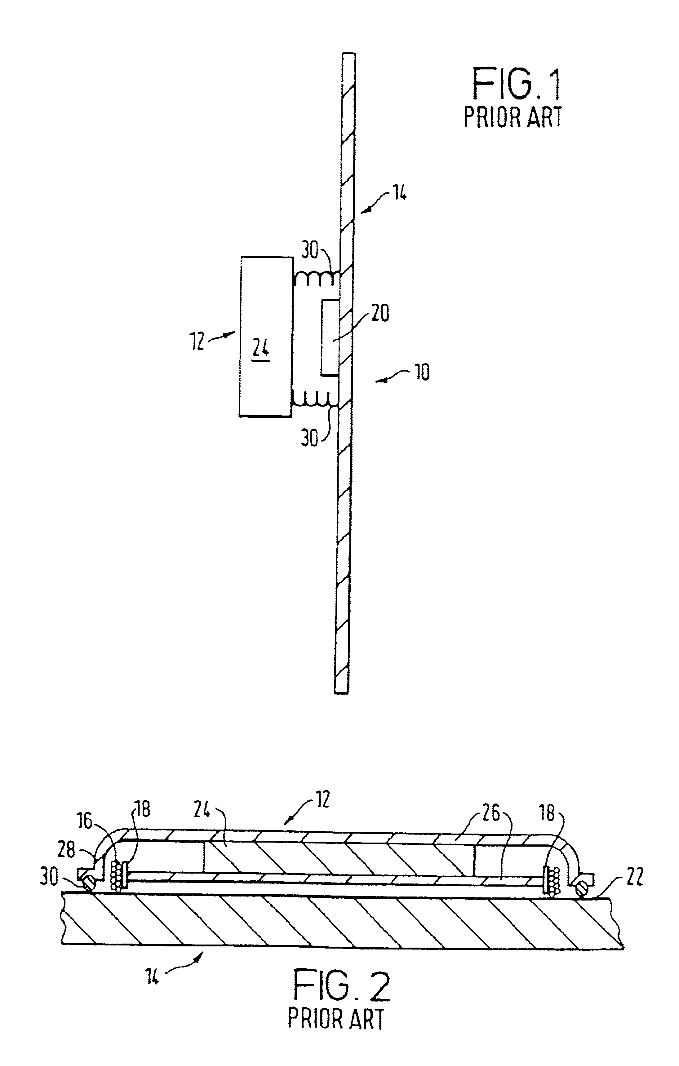
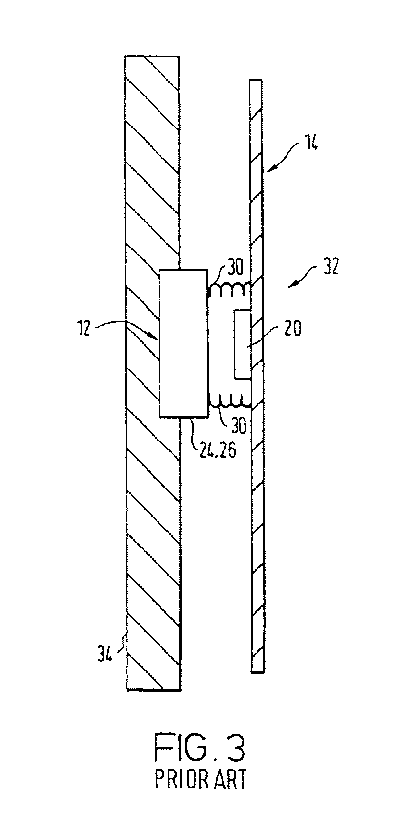
BACKGROUND[0001]The invention relates to loudspeakers of the kind in which an acoustic output is produced by applying bending waves to an acoustic radiator comprising a resonant member, e.g. a panel-form member, to cause it to resonate. Such loudspeakers are described in International patent application WO97 / 09842 of Verity Group plc later assigned to New Transducers Limited.[0002]A vibration exciter for exciting such a resonant member needs a form of fixture onto the member to allow the best possible conversion of drive power into bending waves. An inertial reaction exciter applies a push / pull force to the member by reacting against the inertia of the driver mass and can be suitable.[0003]FIGS. 1 and 2 show a known form of resonant panel-form loudspeaker (10) with one known kind of inertial reaction vibration exciter or transducer (see FIG. 11b of International application WO97 / 09842). (FIG. 1 is schematic, whilst FIG. 2 gives sectional detail of the exciter). Thus while FIG. 1 sho...

Claims


Application Information

Patent Timeline
IPC IPC(8): H04R9/00H04R9/06H04R7/04H04R7/06H04R7/00
CPCH04R9/06H04R7/045H04R7/06H04R9/066
Inventor AZIMA, HENRYCOLLOMS, MARTINROBERTS, MARTINBANK, GRAHAMHARRIS, NEILDJAHANSOUZI, BIJAN
Owner GOOGLE LLC
Learn More