
Remote monitoring diagnostics

a remote monitoring and diagnostic technology, applied in the field of remote monitoring diagnostics, can solve the problems of reducing the efficiency of service technicians, reducing and reducing the need of owners, so as to reduce the number of unnecessary service calls and reduce the need of owners

Inactive Publication Date: 2005-10-18
YORK INT CORP
View PDF14 Cites 123 Cited by
  • Summary
  • Abstract
  • Description
  • Claims
  • Application Information

AI Technical Summary

Benefits of technology

"The present invention is a system for remotely monitoring the operations of a heating ventilating and air conditioning (HVAC) system. The system uses a remote monitoring unit (RMU) located on-site at the facilities of the HVAC system to receive data indicative of the operation of the system and determine if it is operating within normal parameters. If there is a problem, an alarm is generated and the data is stored in memory. The RMU can continue to monitor the source of the alarm to determine if it is temporary or requires remedial action. The RMU can communicate with a remote monitoring diagnostics device (RMD) located at the manufacturer's facility to download the information and determine if there is a problem that requires remedial action. The system allows the HVAC system to be monitored by the manufacturer, reducing the need for the building owner to make decisions regarding the equipment. The manufacturer can also analyze the data to determine the nature of the problem and the appropriate corrective action, reducing unnecessary service calls and improving efficiency. The system uses a one-way line of communication between the RMU and the component equipment, reducing the risk of mischief. The equipment manufacturer can also analyze equipment operation in real-time to quickly establish patterns of operational problems and initiate corrective action before individual component equipment failures occur."

Problems solved by technology

Such systems suffer from a few inadequacies.
First, it fails to recognize that chillers, and frequently rooftop units, already include sensors that monitor operational parameters and transmit this information to the control center.
The control centers provided with chillers differ for each chiller manufacturer, and so accessing the information received by the control centers can prove to be more difficult than rerouting information transmitted from the sensors to such equipment or providing new sensors.
This two-way communication, particularly when set up to operate over the Internet, is subject to mischief by hackers who can cause false exception messages necessitating unnecessary technician service calls, or worse, shutting down the equipment.
Current methods of monitoring the operation of chillers or rooftop units of air conditioning systems currently do not provide the capability to both remotely diagnose an existing problem or anticipate the occurrence of a problem that could result in shut down or improper operation of equipment.
Alternatively, the service technicians may be dispatched to a repair site and may not have the correct parts or equipment to repair the malfunctioning unit.
In another scenario, the technicians are dispatched to repair a malfunctioning unit on an emergency basis, frequently at inconvenient times, after a failure has occurred.
For the technician, this means reduced productivity.
More importantly, it can result in reduced performance to other customers, as the technician(s) is required to respond to reports of malfunctioning units on an emergency basis.
While the system of monitoring is remote and provides important information about the operation of the system, such a system should not, for security reasons, allow a remote user to gain access to the information in the system from his remote location.

Method used


Image

  • Remote monitoring diagnostics
  • Remote monitoring diagnostics
  • Remote monitoring diagnostics

Examples


Embodiment Construction

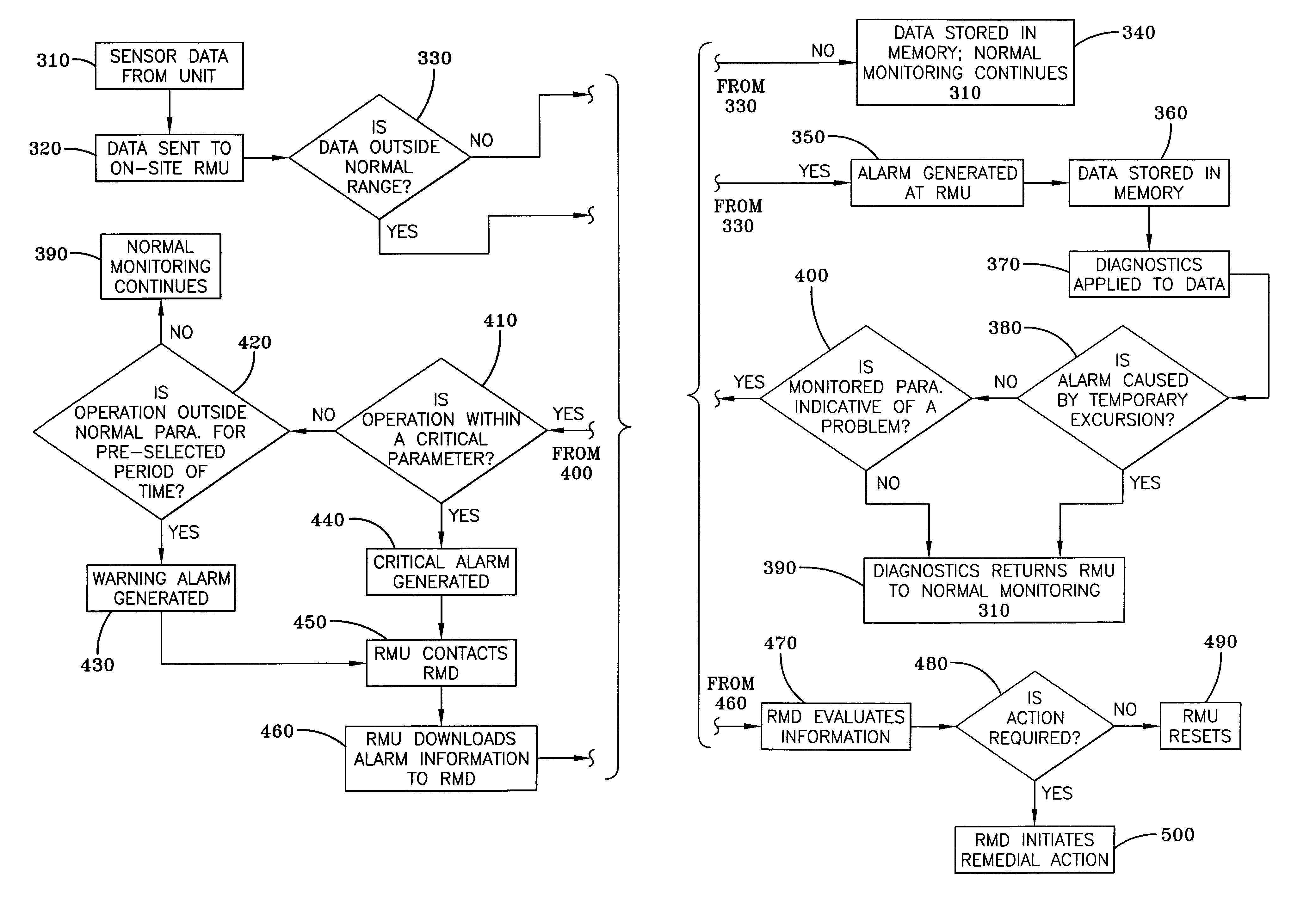
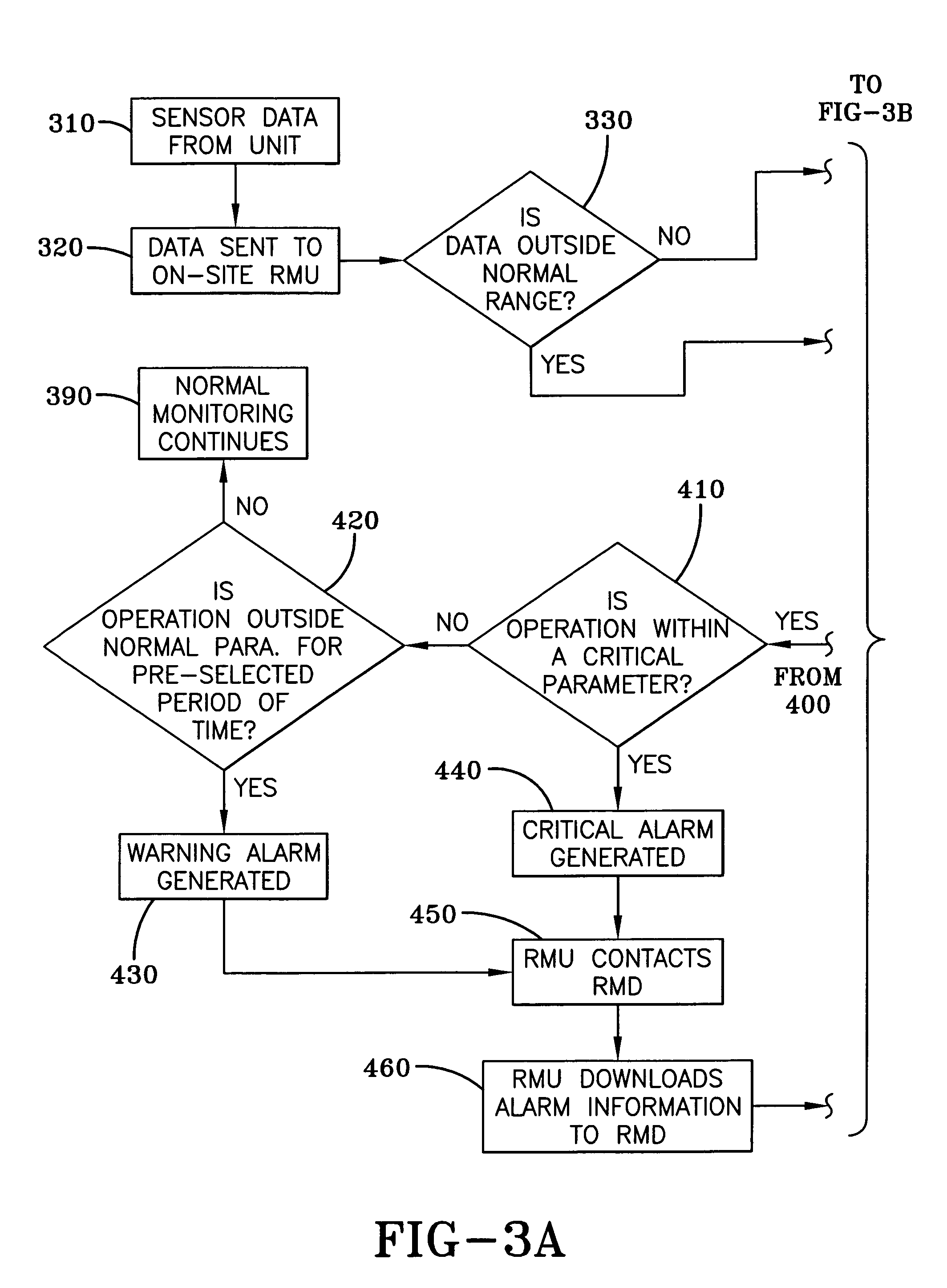
[0021]HVAC equipment requires monitoring to assure that the equipment is operating within specified parameters to assure efficient performance. It is the financial interest of the owner of the equipment to know when the equipment is not operating within specified parameters, as performance outside these parameters can result in higher operating costs in the form of higher energy bills. However, monitoring also may provide information that indicates that routine maintenance is required at intervals that deviate from pre-scheduled intervals. If monitoring indicates that maintenance is required sooner than the pre-scheduled interval, the routine maintenance can be scheduled in advance and inefficient operation can be prevented. If, on the other hand, monitoring indicates that routine maintenance is not required at the pre-scheduled interval, the routine maintenance can be delayed and the owner can avoid payment of an unnecessary routine maintenance check-up. Importantly, monitoring can...


PUM


Abstract

A system for remotely monitoring operations of an HVAC system such as a chiller system having a control center, or a rooftop unit. The system utilizes a remote monitoring unit (RMU) located on-site. The RMU is in one-way communication with the component of the air conditioning system and receives data indicative of the operation of the component and determines whether the component is operating outside the normal operating parameters. When the RMU determines, from the data, that there is a problem that is within a critical parameter range, then a critical alarm is generated and the RMU opens a line of communication with a remote monitoring diagnostics device (RMD) located at the facility of the HVAC or refrigeration manufacturer and downloads the information to the RMD which determines whether remedial action is required and initiates remedial action if required.

Description

FIELD OF THE INVENTION[0001]The present invention is directed to system of remotely monitoring a chiller or a rooftop unit of an air conditioning system.BACKGROUND OF THE INVENTION[0002]Rooftop units are assembled onto the flat roofs of structures such as supermarkets, office buildings and other commercial structures. These units are factory assembled and tested, needing only to be hoisted to the roof at the site for installation. A rooftop unit may be used for heating, cooling or both.[0003]Chillers, or chilled water units, are cost-effective systems that utilize both water and refrigerant. Chillers remove heat from the water, which is then circulated through other components in the system. Water is an excellent secondary refrigerant because it is readily available, inexpensive, non-toxic and substantially non-corrosive. It also has a favorable specific heat value. Other secondary refrigerants can also be used, depending upon the application. These include calcium chloride or sodiu...

Claims


Application Information

Patent Timeline
Patent Type & Authority Patents(United States)
IPC IPC(8): F24F11/00
CPCF24F11/0086F24F2011/0068F24F11/30F24F11/56F24F11/38
Inventor ERDMAN, JR., CLAIR ERNEST
Owner YORK INT CORP
Learn More