Semiconductor laser device

Inactive Publication Date: 2005-10-11
SHARP KK
View PDF9 Cites 3 Cited by
  • Summary
  • Abstract
  • Description
  • Claims
  • Application Information

AI Technical Summary

Benefits of technology

[0004]Accordingly, it is an object of the present invention to provide a semiconductor laser device capable of maintaining a good luminous characteristic under severe environment.
[0008]According to the above constitution, via the opposed lateral apertures of the cap welded or bonded to the stem, air inside the cap is exchanged with air outside the cap. The air effectively cools the laser diode inside the cap. Therefore, the semiconductor laser device is effectively cooled, thereby securing stable operation even if it is incorporated, for example, in CD players for automobile use and in navigation systems using DVD-ROM, and used under severe high-temperature in-vehicle environment.
[0009]Also the cap is in an approximate portal shape, which facilitates manufacturing, thereby improving productivity of the semiconductor laser device.
[0013]According to the above embodiment, in the semiconductor laser device, the cap is attached to the stem so that the lateral apertures of the cap face both end sides of longer side direction of the stem, which makes lateral portions of the cap without apertures face lateral sides of shorter side direction of the stem. This lateral portion effectively protects invasion of foreign substances into the cap from the outside thereof, ensuring effective protection of a laser diode and a wire inside the cap.
[0017]According to the above embodiment, in the semiconductor laser device, the flange portions of the cap are welded or bonded to the arched ridge portion of the stem, thus facilitating manufacturing thereof.
[0021]According to the embodiment, the lateral plate portions of the cap are welded or bonded to the flat portion of the stem, so that the lateral apertures and the reinforcing plate portions of the cap are disposed on the position corresponding to the both ends of longer side direction of the stem. Therefore, the both ends of the longer side direction of the stem and the end face facing the cap side are free from, for example, the flange of the cap, and therefore the end face of the stem has relatively large free area. While the end face of the stem having relatively large free area is brought into contact with a support portion of a pickup unit, the semiconductor laser device is moved against the supporting portion, which enables highly accurate and easy positioning of the semiconductor laser device against the pickup unit.

Problems solved by technology

Eventually, the temperature of the semiconductor laser device is raised, which causes a problem that deterioration of luminous efficiency and change of emission wavelength may easily occur.

Method used


Image

  • Semiconductor laser device
  • Semiconductor laser device
  • Semiconductor laser device

Examples


Embodiment Construction

[0030]Hereinbelow, the present invention will be described in detail in conjunction with embodiments with reference to the drawings.

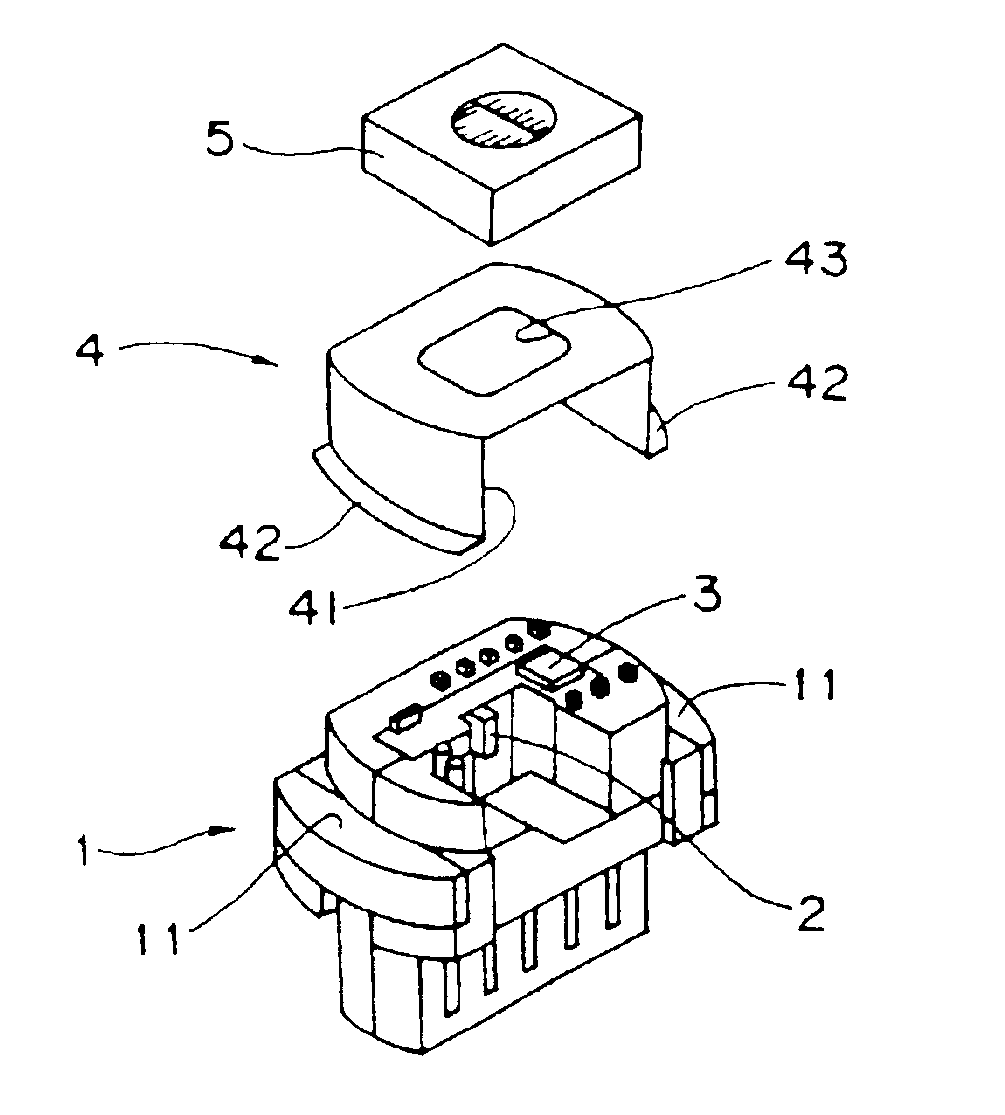
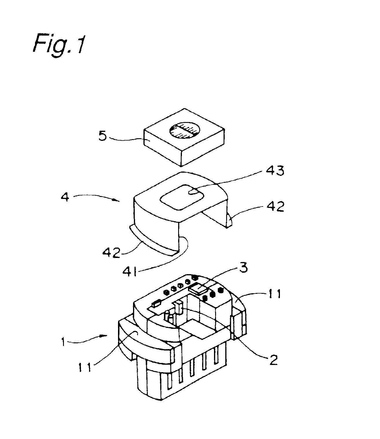
[0031]FIG. 1 is an exploded perspective view showing a semiconductor laser device in an embodiment of the present invention. The semiconductor laser device has a stem 1 composed of a metal portion mainly made of iron and a resin portion, and the stem 1 has metallic lead pins to be electrically connected to a component mounted on the stem 1 and external wiring terminals to be connected to the lead pins and external wirings. A laser diode 2 and a light receiving element 3 are mounted on the stem 1, and the laser diode 2 and light receiving element 3 are electrically connected to the lead pins through an unshown wire. It is noted that a monitor diode (unshown) for optical output adjustment is usually disposed between the laser diode 2 and the stem 1. The stem 1 has arched protruding ridge portions 11, 11 on the both ends of longer side direction.

[0032]On t...


PUM


Abstract

There is provided a semiconductor laser device capable of maintaining a good luminous characteristic under severe environment. A cap 4 in an approximate portal shape having lateral apertures 41 is attached to a stem 1 on which a laser diode 2 and a light receiving element 3 are mounted. A holographic element 5 is mounted on a window 43 of the cap 4. Air inside the cap 4 is exchanged with outside air through the lateral apertures 41 to effectively cool the laser diode 2, thus enabling the semiconductor laser device to maintain a good luminous characteristic under high-temperature severe environment.

Description

BACKGROUND OF THE INVENTION[0001]The present invention relates to a semiconductor laser device.[0002]Conventionally, there have been semiconductor laser devices to be incorporated in pickup units of information recording and reproducing apparatuses for personal computers as shown in FIG. 7. Such semiconductor laser device includes a stem 101 having a laser diode 102 and a light receiving element 103 mounted thereon, a protect cap 104 welded or bonded to the stem 101 for protecting the laser diode 102 and the light receiving element 103, and a holographic element 105 mounted on the protect cap 104. The protect cap 104 has a structure without an aperture for sealingly enclosing the laser diode 102 and the light receiving element 103 so that the laser diode 102 and the like is not affected by dust or foreign substances from the outside.[0003]Recently, the pickup units have been commonly and widely applied to CD (Compact Disk) players for automobile use and to car navigation systems usi...

Claims


Application Information

Patent Timeline
IPC IPC(8): H01S5/00H01S5/024H01S5/022G11B7/125
CPCH01S5/02212H01S5/02469H01S5/02292H01L2224/48091H01L2924/00014H01S5/02255
Inventor CHIDA, ATSUSHI
Owner SHARP KK
Why Eureka
Try Eureka