
Multi-source power switching circuit for Wake On LAN ethernet application

a multi-source power switching and wake technology, applied in data switching details, instruments, high-level techniques, etc., can solve the problems of expensive design and inability to support wake on lan functionality, and achieve the effect of preventing back powering of the pci bus

Active Publication Date: 2005-10-04
NAT SEMICON CORP
View PDF6 Cites 18 Cited by
  • Summary
  • Abstract
  • Description
  • Claims
  • Application Information

AI Technical Summary

Benefits of technology

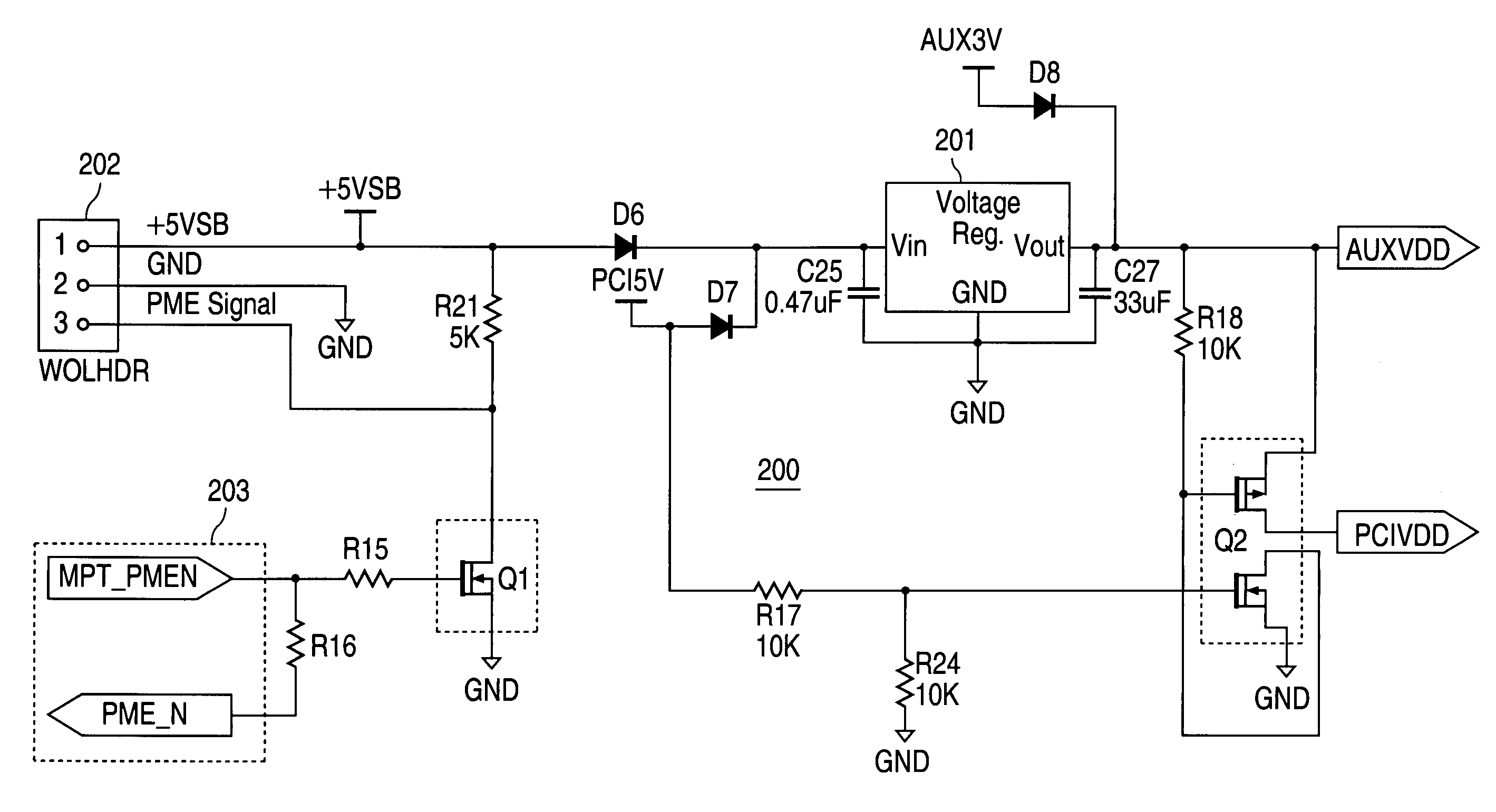
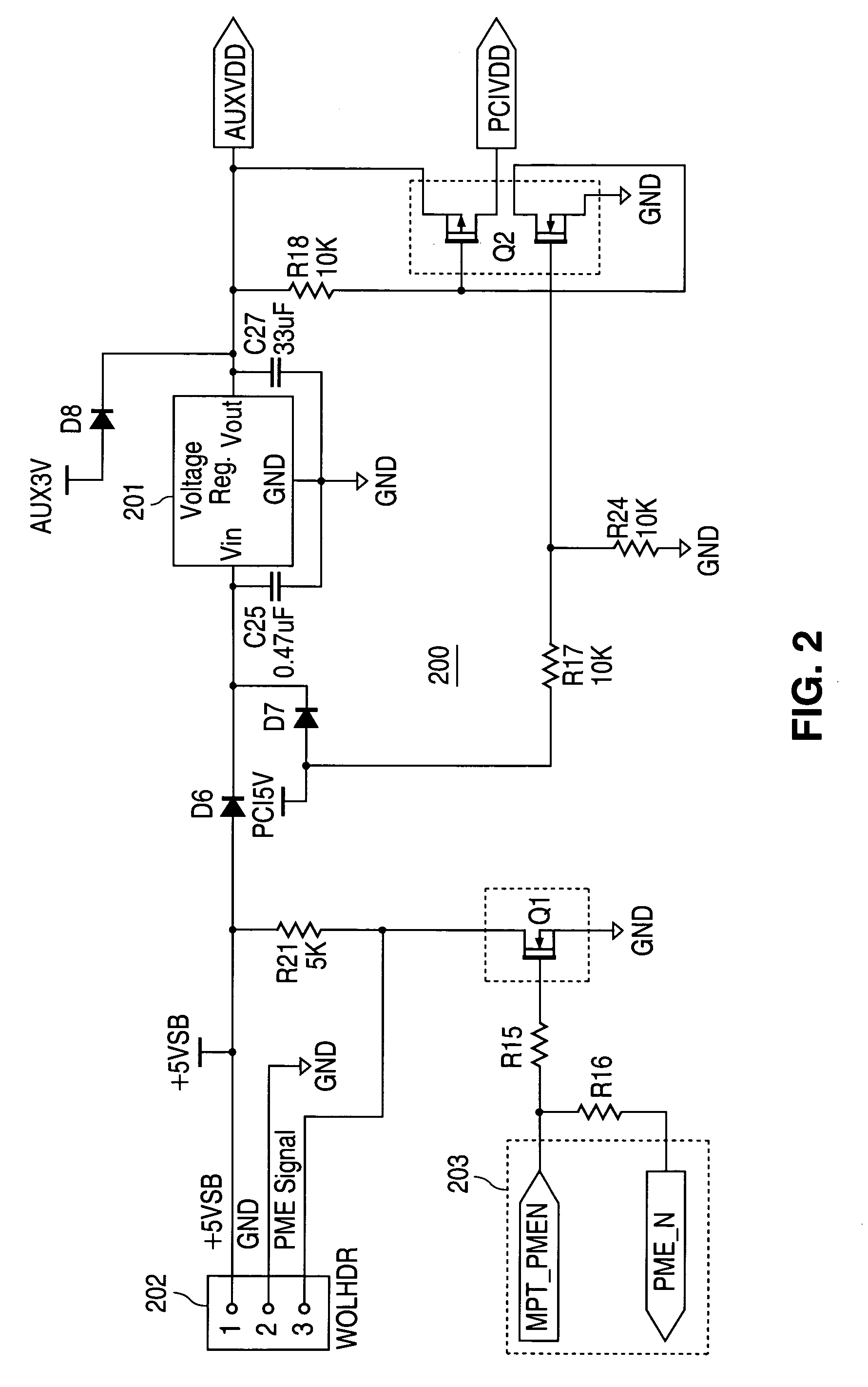
[0005]To address the above-discussed deficiencies of the prior art, it is a primary object of the present invention to provide, for use in a network interface card (NIC) controller, a power and power management signaling circuit for all known Wake On LAN PCI bus configurations that includes only a single voltage regulator. The circuit provides for connections to a network-initiated power management recovery signal MPT—PMEN from the network interface, power management recovery and auxiliary power signals PME—N and AUX3V within the PCI bus, and a system motherboard header. A first inverter inverts MPT—PMEN to the PME signal for the header, while a second inverter gates auxiliary power AUXVDD to main power PCIVDD for the NIC when the PCI system power PCI5V is asserted. Diodes prevent back powering of the PCI bus during hibernate states, system power short circuiting and leakage malfunctions when the header is incorrectly connected or unconnected, and auxiliary power shorts to ground when the previously undefined AUX3V PCI bus line is grounded.

Problems solved by technology

However, some systems do not support Wake On LAN functionality (or “network-initiated power management recovery”), while others support such functionality but utilize different mechanisms.
Current solutions typically employ independent voltage regulators for each of the different mechanisms and / or power requirements, an expensive design.

Method used


Image

  • Multi-source power switching circuit for Wake On LAN ethernet application
  • Multi-source power switching circuit for Wake On LAN ethernet application
  • Multi-source power switching circuit for Wake On LAN ethernet application

Examples


Embodiment Construction

[0011]FIGS. 1 and 2, discussed below, and the various embodiments used to describe the principles of the present invention in this patent document are by way of illustration only and should not be construed in any way to limit the scope of the invention. Those skilled in the art will understand that the principles of the present invention may be implemented in any suitably arranged device.

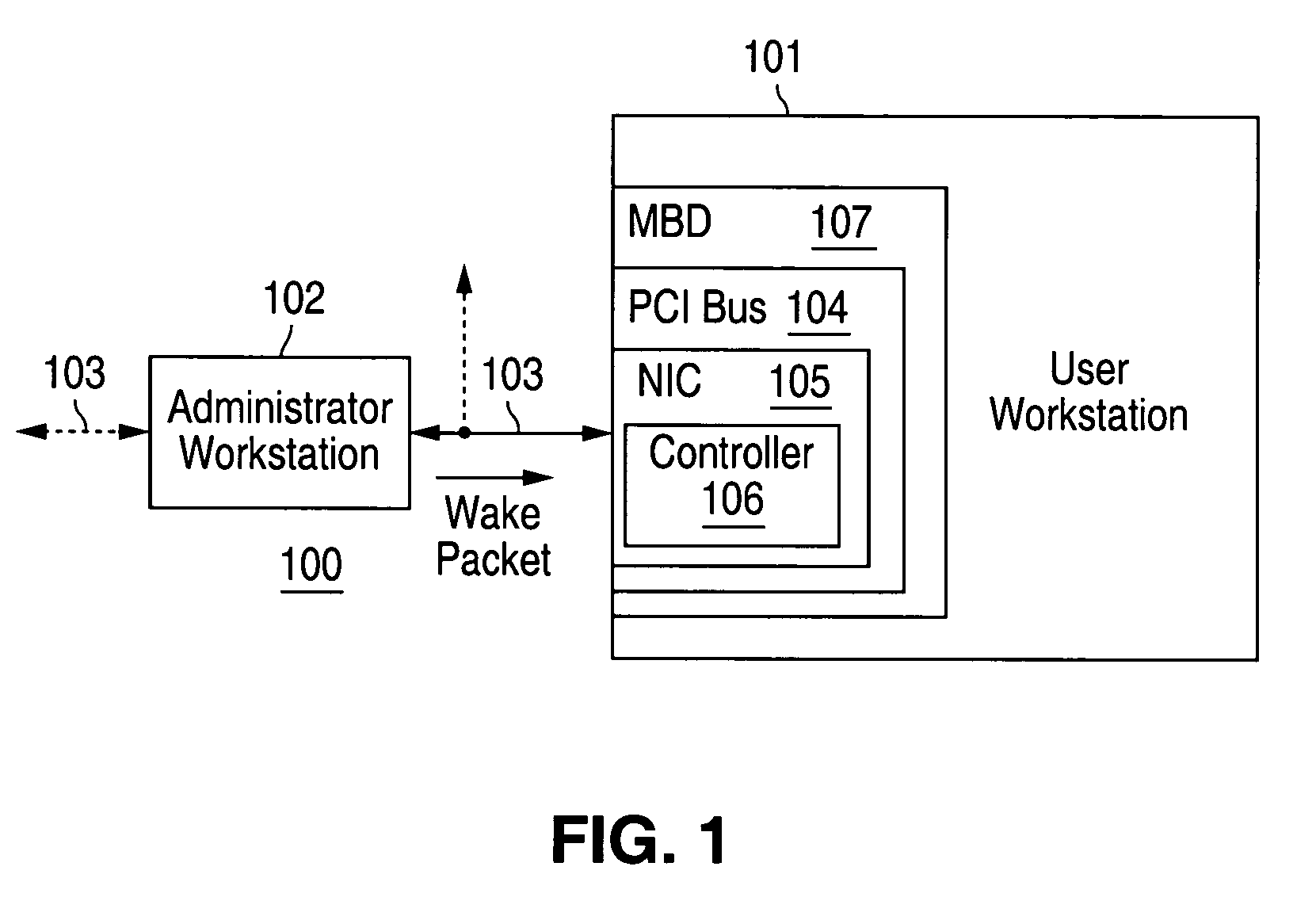
[0012]FIG. 1 depicts a data processing system network including a network interface card supporting multiple power requirements and power management signaling configurations with a single voltage regulator according to one embodiment of the present invention. Data processing system network 100 includes a plurality of data processing systems 101–102 communicably coupled to each other, as well as to other data processing systems (not shown), by a network connection 103. The infrastructure represented by network connection 103 may comprise, for example, an Ethernet local area network (LAN).

[0013]The c...


PUM


Abstract

A power and power management signaling circuit in a network interface card (NIC) for all known Wake On LAN PCI bus configurations includes a single voltage regulator together with connections to a network-initiated power management recovery signal MPT—PMEN from the network interface, power management recovery and auxiliary power signals PME—N and AUX3V within the PCI bus, and a system motherboard header. A first inverter inverts MPT—PMEN to the PME signal for the header, while a second inverter gates auxiliary power AUXVDD to main power PCIVDD for the NIC when the PCI system power PCI5V is asserted. Diodes prevent back powering of the PCI bus during hibernate states, system power short circuiting and leakage malfunctions when the header is incorrectly connected or unconnected, and auxiliary power shorts to ground when the previously undefined AUX3V PCI bus line is grounded.

Description

TECHNICAL FIELD OF THE INVENTION[0001]The present invention is directed, in general, to data processing system power management over networks and, more specifically, to providing power within network interface cards which may be installed in a variety of different environments including systems supporting network power management.BACKGROUND OF THE INVENTION[0002]Power management schemes for data processing systems such as desktop computers allow the system to suspend power to one or more selected components during extended periods of inactivity. Systems “wake up” from power saving states when the user touches the keyboard or mouse, or some other user input device is actuated. In addition, “Wake On Lan” capability has been developed for many systems, allowing a system administrator to wake any system connected to a network and check the status of that system via the network.[0003]The Peripheral Component Interconnect (PCI) bus standard is one architecture within which network power m...

Claims


Application Information

Patent Timeline
IPC IPC(8): G06F1/32G06F1/26H04L12/12
CPCG06F1/26G06F1/3209H04L12/12Y02B60/34Y02B60/35Y02D30/50
Inventor MILLER, DAVID J.
Owner NAT SEMICON CORP
Learn More