
Cable end connector assembly having pulling device

a technology of pulling device and cable end connector, which is applied in the direction of connection, coupling device connection, electrical apparatus, etc., can solve the problems of inconvenient or even difficult for users to hold the cable end connector

Inactive Publication Date: 2005-10-04
HON HAI PRECISION IND CO LTD
View PDF8 Cites 19 Cited by
  • Summary
  • Abstract
  • Description
  • Claims
  • Application Information

AI Technical Summary

Benefits of technology

[0008]Accordingly, the object of the present invention is to provide a cable end connector assembly having a pulling device for detaching the cable end connector assembly from a complementary connector more conveniently when a plurality of vertical or angularly extending wires are included with the cable end connector assembly.
[0009]In order to achieve the above-mentioned object, a cable end connector assembly in accordance with the present invention includes an insulative housing, a plurality of contacts received in the housing, a plurality of wires terminated to the contacts, a cover over-molded with portions of the housing and the cable, a locking member slideably assembled to the cover and the housing, and a pulling device for facilitating operation of the locking member. The locking member includes a pair of latch portions for latching with a complementary connector and an oblique portion. The pulling device includes an acting portion engaging with the oblique portion of the locking member and a handling portion at a rear end thereof. When the pulling device is rearwardly pulled, the oblique portion moves downwardly and rearwardly and deflects the latch portions to unlock from the complementary connector.

Problems solved by technology

However, in a situation where the plurality of wires of the cable end connector assembly disposed near the locking member extend in a direction perpendicular to or angular with a mating direction of the cable end connector assembly, when attempting to separated the cable end connector assembly from the complementary connector, it is inconvenient or even difficult for a user to hold the cable end connector assembly and operate the locking member in the direction perpendicular to the mating direction.

Method used


Image

  • Cable end connector assembly having pulling device
  • Cable end connector assembly having pulling device
  • Cable end connector assembly having pulling device

Examples


Embodiment Construction

[0020]Reference will now be made to the drawing figures to describe the present invention in detail.

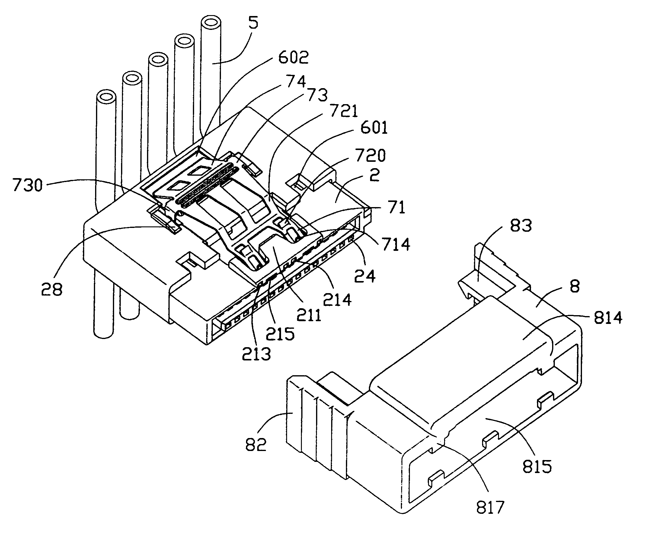
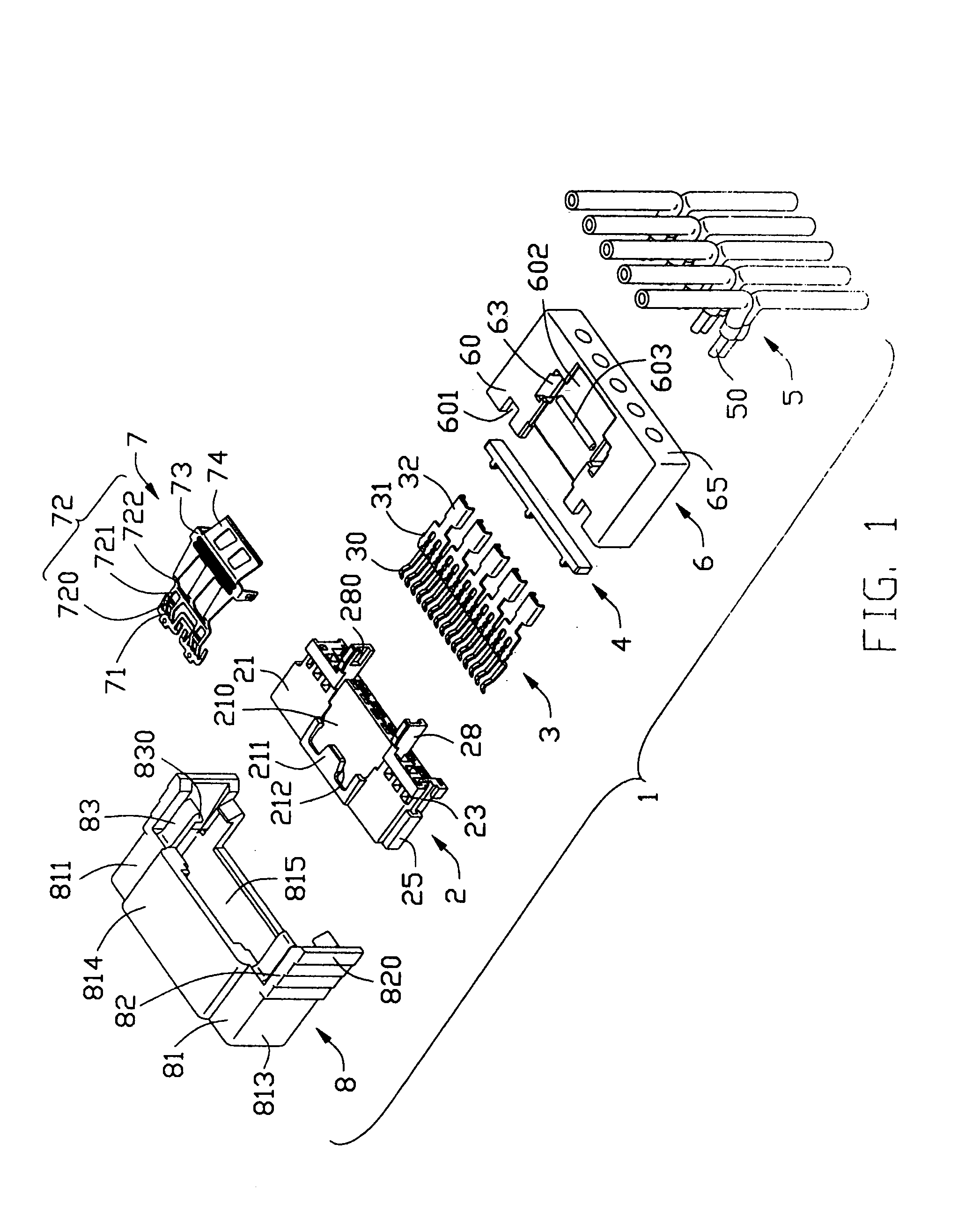
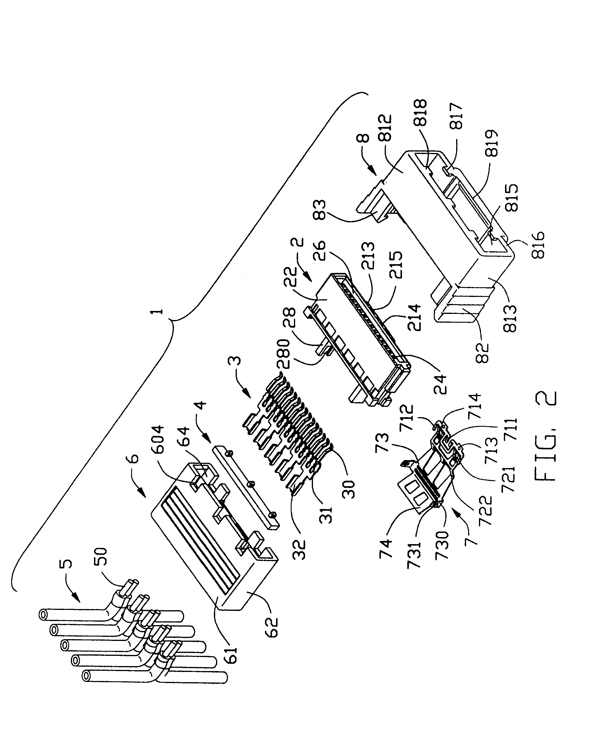
[0021]Referring to FIGS. 1 and 2, a cable end connector assembly 1 in accordance with the present invention comprises an insulative housing 2, a plurality of contacts 3, a spacer 4, a plurality of wires 5, an insulative cover 6, a locking member 7 and a pulling device 8.

[0022]Referring to FIGS. 1–2 in conjunction with FIG. 6, the insulative housing 2 comprises an upper wall 21, a lower wall 22 opposite to the upper wall 21, and a pair of sidewalls 23 connecting with the upper wall 21 and the lower wall 22. A guiding projection 25 projects outwardly from one sidewall 23 for guiding a proper insertion of a complementary connector. An L-shaped receiving space 26 is defined between the upper and the lower walls 21, 22. A plurality of passageways 24 is defined through the lower walls 22 along a front-to-back direction. The upper wall 21 defines a depression 210 on an upper surface thereof....


PUM


Abstract

A cable end connector assembly (1) includes an insulative housing (2), a plurality of contacts (3) received in the housing, a plurality of wires (5) terminated to the contacts, a cover (6) over-molded with portions of the housing and the cable, a locking member (7) slideably assembled to the cover and the housing, and a pulling device (8). The locking member includes a pair of latch portions (720) for latching with a complementary connector and an oblique portion (722). The pulling device includes an acting portion (819) engaging with the oblique portion of the locking member, and a handling portion (82) at a rear end thereof. When the pulling device is rearwardly pulled, the oblique portion moves downwardly and rearwardly and deflects the latch portions to unlock from the complementary connector.

Description

CROSS-REFERENCE TO RELATED APPLICATIONS[0001]This application is related to U.S. patent application Ser. No. 10 / 776,111 filed on Feb. 10, 2004 and entitled “CABLE END CONNECTOR ASSEMBLY HAVING LOCKING MEMBER”, and U.S. patent application Ser. No. 10 / 797,979 filed on Mar. 10, 2004 and entitled “CABLE END CONNECTOR ASSEMBLY HAVING LOCKING MEMBER”, both of which have the same applicant and assignee as the present invention. The disclosure of these related applications is incorporated herein by reference.BACKGROUND OF THE INVENTION[0002]1. Field of the Invention[0003]The present invention generally relates to a cable end connector assembly, and more particularly to a cable end connector assembly having a pulling device.[0004]2. Description of Prior Art[0005]There exits in the art an electrical connector known as a serial Advanced Technology Attachment (serial ATA) connector which is generally used for disk drives and storage peripherals. Especially, the serial ATA connector according to...

Claims


Application Information

Patent Timeline
Patent Type & Authority Patents(United States)
IPC IPC(8): H01R13/627H01R13/633
CPCH01R13/6275H01R13/633
Inventor WU, JERRY
Owner HON HAI PRECISION IND CO LTD
Learn More