
Camera that controls image sensor exposure

a technology of image sensor and exposure sensor, applied in the field of cameras, can solve the problems of inability to photograph the subject with appropriate brightness, low brightness of the subject, and dark photographs

Inactive Publication Date: 2005-09-27
XACTI CORP
View PDF12 Cites 36 Cited by
  • Summary
  • Abstract
  • Description
  • Claims
  • Application Information

AI Technical Summary

Benefits of technology

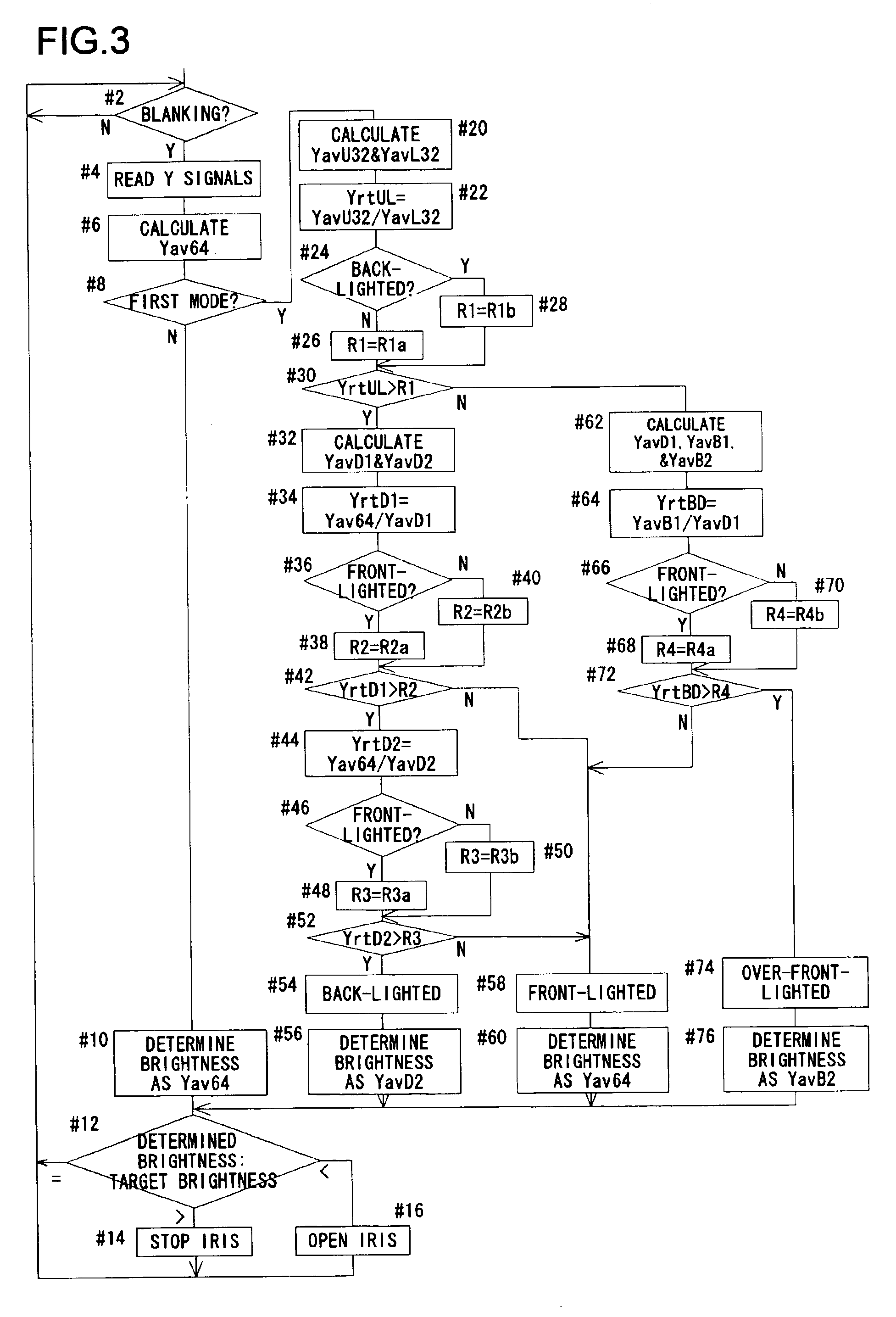
[0014]This camera distinguishes among three conditions in terms of the brightness of the subject relative to that of the background, and performs AE control according to the result. The first, second, and third conditions correspond to a front-lighted, a back-lighted, and an over-front-lighted condition, respectively. Distinguishing not only a front-lighted and a back-lighted condition but also an over-front-lighted condition helps prevent erroneously recognizing an over-front-lighted condition as a back-lighted condition, and thus makes it possible to photograph the subject always with appropriate brightness. In a video camera or digital camera, the photoelectric conversion device itself that is used as an image sensor therein can be used as a means for detecting brightness. In a camera that uses photographic film as an image sensor, a means for detecting brightness needs to be provided separately.
[0026]When the first condition is recognized, in which there is little difference in brightness between the subject and the background, using the overall average, which is the average of brightness over all the regions, as the brightness of the subject makes it possible to photograph the subject with appropriate brightness. When the second condition is recognized, in which the brightness of the subject is remarkably low relative to that of the background, using the second dark-region average, which is the average of brightness in regions in which brightness is particularly low, as the brightness of the subject makes it possible to photograph the subject with appropriate brightness. When the third condition is recognized, in which the brightness of the subject is remarkably high relative to that of the background, using the second bright-region average, which is the average of brightness in regions in which brightness is particularly high, as the brightness of the subject makes it possible to photograph the subject with appropriate brightness.

Problems solved by technology

However, in a back-lighted condition in which the subject is illuminated from behind and the brightness of the subject is extremely low relative to the brightness of the background, the subject photographed appears dark.
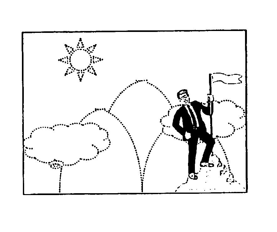
However, a subject does not always lie in a central or lower portion of an area to be photographed, and this often makes it impossible to photograph the subject with appropriate brightness. FIG. 7 shows an example of brightness distribution that poses such a problem. FIG. 7 shows a subject (for example, two persons) lying in a left-hand end and a right-hand end portion of the area to be photographed in a back-lighted condition.
Thus, simply distinguishing a front-lighted and a back-lighted condition does not permit a subject to be photographed with appropriate brightness in an over-front-lighted condition.

Method used


Image

  • Camera that controls image sensor exposure
  • Camera that controls image sensor exposure
  • Camera that controls image sensor exposure

Examples


Embodiment Construction

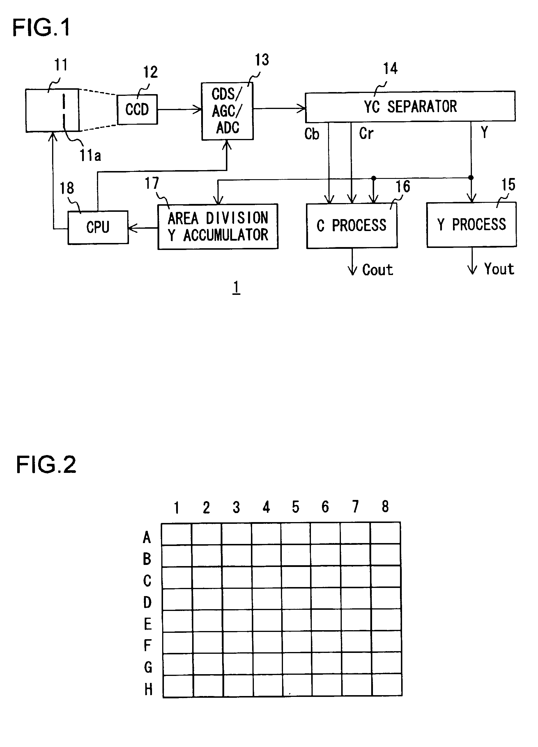
[0036]Hereinafter, a video camera embodying the present invention will be described with reference to the drawings. An outline of the configuration of the video camera (hereinafter referred to simply as the “camera” also) of this embodiment is shown in FIG. 1. The camera 1 is provided with a taking lens 11, a CCD 12 serving as an image sensor, an analog processing circuit 13, a YC separator circuit 14, a Y process circuit 15, a C process circuit 16, a Y accumulator circuit 17, and a CPU 18.

[0037]The taking lens 11 images the light from an area to be photographed on the light-sensing surface of the CCD12. The taking lens 11 is provided with an aperture stop (iris) 11a of which the aperture diameter is variable. Thus, by varying the aperture diameter of the aperture stop 11a, it is possible to adjust the exposure of the CCD 12.

[0038]The CCD 12 performs photographing by converting light into electric signals. The pixels of the CCD 12 are each provided with a filter that selectively tra...


PUM


Abstract

An automatic exposure control camera always permits a subject to be photographed with appropriate brightness regardless of a front-lighted, back-lighted, or over-front-lighted condition. The area to be photographed is divided into 64 regions. The camera determines the average Yav64 of brightness over all the regions, the average YavU32 of brightness in the regions constituting the upper half, the average YavL32 of brightness in the regions constituting the lower half, the average YavD1 of brightness in regions in which brightness is lower than the average Yav64, the average YavD2 of brightness in regions in which brightness is lower than the average YavD1, the average YavB1 of brightness in regions in which brightness is higher than the average Yav64, and the average YavB2 of brightness in regions in which brightness is higher than the average YavB1. Based on the ratios between these averages, the camera distinguishes among a front-lighted, a back-lighted, and an over-front-lighted condition and controls the exposure of an image sensor accordingly.

Description

BACKGROUND OF THE INVENTION[0001]1. Field of the Invention[0002]The present invention relates to a camera having a function of controlling the exposure of an image sensor so that a subject is photographed with appropriate brightness.[0003]2. Description of the Prior Art[0004]A camera is provided with an automatic exposure (AE) control function for controlling the exposure of an image sensor according to the brightness of a subject so that the subject, i.e. the main object to be photographed, is photographed with appropriate brightness. Such an AE function is provided not only in cameras such as video cameras and digital cameras that perform photoelectric conversion as an image sensor but also in cameras that use sensitized film as an image sensor.[0005]In general, an AE function is achieved by determining the average brightness over a whole area that is going to be photographed and then adjusting the aperture diameter of an iris, or an aperture stop, so that the brightness so determ...

Claims


Application Information

Patent Timeline
Patent Type & Authority Patents(United States)
IPC IPC(8): G03B7/08G03B7/28H04N5/235G03B19/02H04N23/12H04N23/75
CPCG03B7/08G03B7/28H04N5/2351H04N23/71
Inventor MORI, YUKIOOKADA, SEIJIMISE, TETSUOHASEGAWA, SHOICHI
Owner XACTI CORP
Learn More