
Tuning fork-type crystal vibrator

a technology of tuning forks and crystals, applied in piezoelectric/electrostrictive devices, device material selection, device materials, etc., can solve the problems of not being able to achieve even smaller ci values or, in particular, better frequency change characteristics (electrical shock resistance) with regard to drops or impacts, and the support of tuning forks on the tuning forks is large, so as to achieve the effect of suppressing vibration leakage due to the pair of tuning fork arms

Inactive Publication Date: 2005-09-27
NIHON DEMPA KOGYO CO LTD
View PDF8 Cites 12 Cited by
  • Summary
  • Abstract
  • Description
  • Claims
  • Application Information

AI Technical Summary

Benefits of technology

The present invention is based on an improvement in the design of a tuning fork-shaped crystal vibrator. By improving the asymmetry of the left and right masses with respect to the center line bisecting the tuning fork-shaped crystal element in the width direction, the vibrator can have better shock resistance and reduced vibration leakage. This is achieved by shifting the tip of the tuning fork slit in a way that balances the mass with respect to the center of the vibrations. This design also stabilizes the adhesion of the tuning fork-shaped crystal element with an electrically conductive adhesive and reduces the occurrence of stress due to asymmetry of mass. Overall, this invention improves the performance and reliability of tuning fork-shaped crystal vibrators.

Problems solved by technology

However, in the tuning fork-type vibrator with the above-described configuration, even though the tuning fork-shaped crystal element 1 can be made small, and even though a CI value specified to less than 90 kΩ can be attained by providing the pair of tuning fork arms 3a and 3b with the grooves 4 and a high mechanical strength (mechanical shock resistance) preventing damage or breaking off of the tuning fork-shaped crystal element through drops or impacts can be achieved by ensuring a large application surface area of the electrically conductive resin, there was the problem that it was not possible to attain an even smaller CI value or, in particular, better frequency change characteristics (electrical shock resistance) with regard to drops or impacts.
When the surface area over which the electrically conductive adhesive 6 is applied is large, then the adhesive strength is high and the mechanical shock resistance is improved, but the influence that this manner of support has on the tuning fork vibrations becomes large, and the electrical shock resistance, such as frequency changes in response to drops or impacts becomes poor.
In particular, when the length of the pair of tuning fork arms 3a and 3b is large, a shift of the center of the tuning fork vibrations from the geometrical center has a large adverse effect on the balance of the tuning fork vibrations.
Furthermore, the etching of the tuning fork slit is restricted.
Consequently, there was the problem that the frequency change characteristics with regard to drops or impacts are worsened, so that the electrical shock resistance cannot be improved.
Needless to say, the mechanical shock resistance, such as resistance against breakage in case of drops or impacts, is also worsened.
In these cases, the CI value of the tuning fork-type crystal vibrator can be made to satisfy the specified CI value for example by increasing the depth of the grooves 4, but it was not possible to prevent a change for the worse, in particular, the frequency change characteristics with regard to drops or impacts (electrical shock resistance).
Thus, there was the serious problem of how to improve the electrical shock resistance in order to realize a small tuning fork-type crystal vibrator in which the planar outer dimensions of the tuning fork-shaped crystal element are not larger than 2.3 mm×0.5 mm, for example.
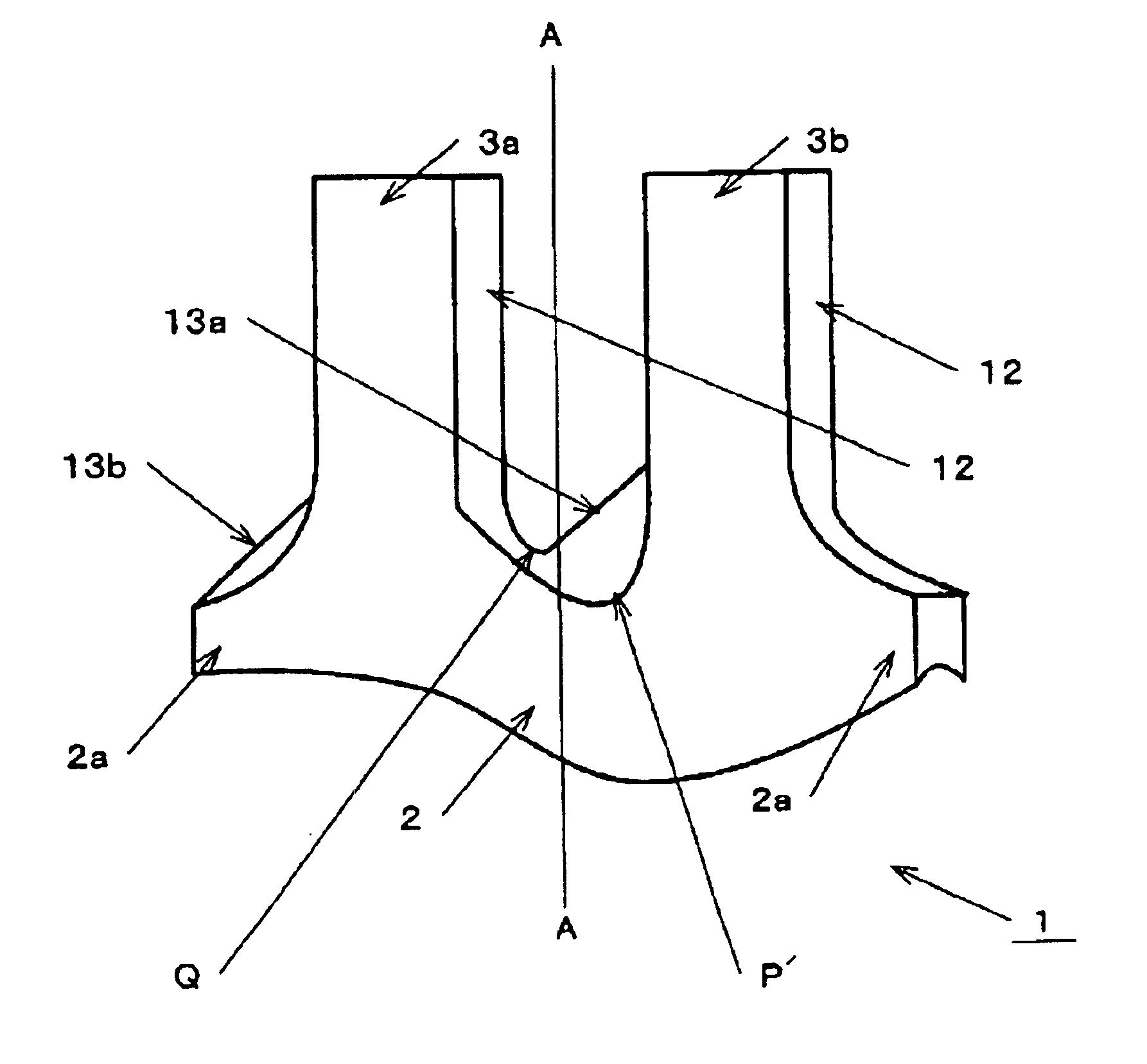
It should be noted that the base protrusion portions 2a may have the affect of reducing the asymmetry due to the first slanted portion 13a, but there was the problem that this alone is insufficient.

Method used


Image

  • Tuning fork-type crystal vibrator
  • Tuning fork-type crystal vibrator
  • Tuning fork-type crystal vibrator

Examples


embodiments

[0041]FIG. 1 is a diagram illustrating an embodiment of a tuning fork-type vibrator in accordance with the present invention. It should be noted that portions identical to the above-described conventional example are denoted by identical numerals and their further explanation has been omitted.

[0042]The tuning fork-type vibrator includes a tuning fork-shaped crystal element 1, formed by etching and made of a pair of tuning fork arms 3a and 3b having grooves 4 in both of their principal surfaces as described above, and a tuning fork base portion 2 that is wider than the pair of tuning fork arms 3a and 3b and that has two-level base protrusion portions 2a. Due to etching anisotropy, the tuning fork-shaped crystal element 1 has a first slanted portion 13a and a second slanted portion 13b rising from the −X direction to the +X direction in the tuning fork slit and on the slope of the base protrusion portion 2a on the −X side, respectively.

[0043]Here, the first slanted portion 13a of the ...


PUM


Abstract

A tuning fork-type crystal vibrator is provided that has improved CI and shock resistance. The tuning fork-type crystal vibrator includes a tuning fork-shaped crystal element made of a pair of tuning fork arms having grooves in their principal surfaces, and a tuning fork base portion from which the pair of tuning fork arms extends, an outer shape of the tuning fork-shaped crystal element being processed by etching. The tuning fork-type crystal vibrator has a protrusion, formed due to anisotropy of said etching, on a +X surface of the lateral faces of the tuning fork-shaped crystal element, and a first slanted portion rising from a −X direction in a +X direction formed in a tuning fork slit. A tip of the tuning fork slit on a principal surface side is shifted in +X direction from a center line bisecting the tuning fork-shaped crystal element in a width direction to a position at which tuning fork vibrations of the pair of tuning fork arms are balanced.

Description

BACKGROUND OF THE INVENTION[0001]1. Field of the Invention[0002]The present invention relates to tuning fork-type crystal vibrators (also referred to as “tuning fork-type vibrators” hereinafter) having grooves in both principal surfaces of a pair of tuning fork arms, and in particular to subminiature tuning fork-type vibrators whose shock resistance is improved and whose crystal impedance (also referred to as “CI” hereinafter) is kept small.[0003]2. Description of the Related Art[0004]Tuning fork-type vibrators are widely used as signal sources for keeping time in wrist watches, and in recent years, they have come to be used as synchronization signal sources in portable electronic devices. Thus, as electronic devices are becoming smaller, there is a growing demand for smaller tuning fork-type vibrators.[0005]FIG. 7A and FIG. 7B are diagrams illustrating a conventional example of a tuning fork-type vibrator. FIG. 7A is a diagrammatic view of a tuning fork-type vibrator and FIG. 7B is...

Claims


Application Information

Patent Timeline
Patent Type & Authority Patents(United States)
IPC IPC(8): H03H9/00H03H9/21H01L41/18H03H9/19H01L41/09H03H9/215
CPCH03H9/21
Inventor ONO, KOZOISHIHARA, MINORUKAWANISHI, SHINGO
Owner NIHON DEMPA KOGYO CO LTD
Learn More