
Electrical hand tool machine with vibration damped striking mechanism

Active Publication Date: 2005-09-27
HILTI AG
View PDF7 Cites 29 Cited by
  • Summary
  • Abstract
  • Description
  • Claims
  • Application Information

AI Technical Summary

Benefits of technology

The invention is a vibration-damped striking mechanism module with a low-fatigue current supply for an electrical hand tool machine. The module has a flexible wiring bridge with a plurality of non-vibrationally fastened electrical lines that form a virtually vibration-free module. The wiring bridge has guide means for individual locking guidance and fastening means for discrete site fastening. The wiring bridge is made of plastic and has high and low-fatigue vibration damping results via its viscoelastic behavior. The plug connector is secure and displaceable using an assembly screw. The wiring bridge is pre-installable and bonded to the electronics module. The invention provides a more reliable and efficient electrical hand tool machine with improved vibration damping and current supply.

Problems solved by technology

Such long, freely suspended lines have a very low resistance to bending because of their punctiform cross section and have a low intrinsic resonance relative to bending vibration modi, which can undergo a resonant excitation in the event of vibrations and which can result in failure due to material fatigue.

Method used


Image

  • Electrical hand tool machine with vibration damped striking mechanism
  • Electrical hand tool machine with vibration damped striking mechanism
  • Electrical hand tool machine with vibration damped striking mechanism

Examples


Embodiment Construction

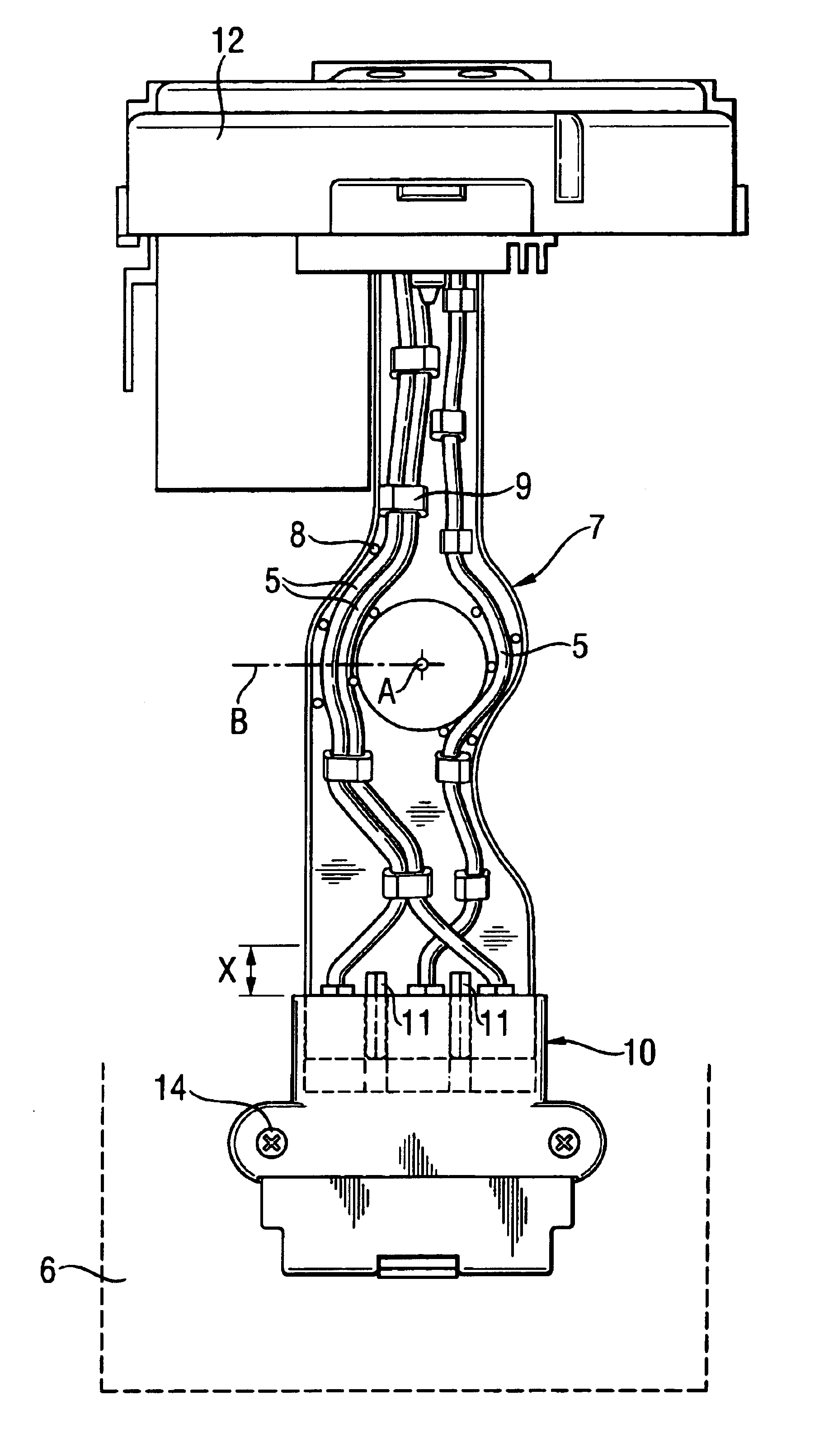
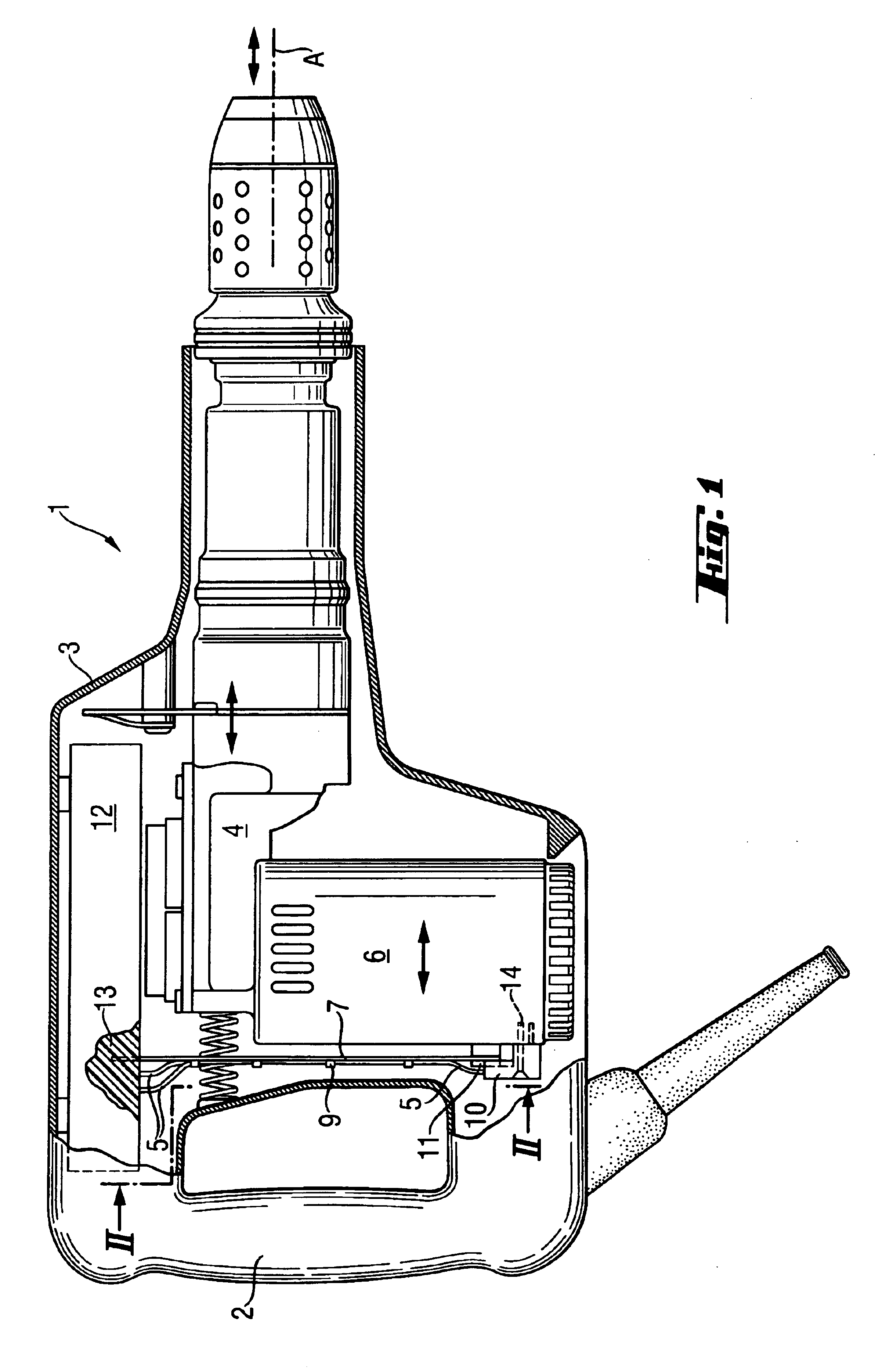
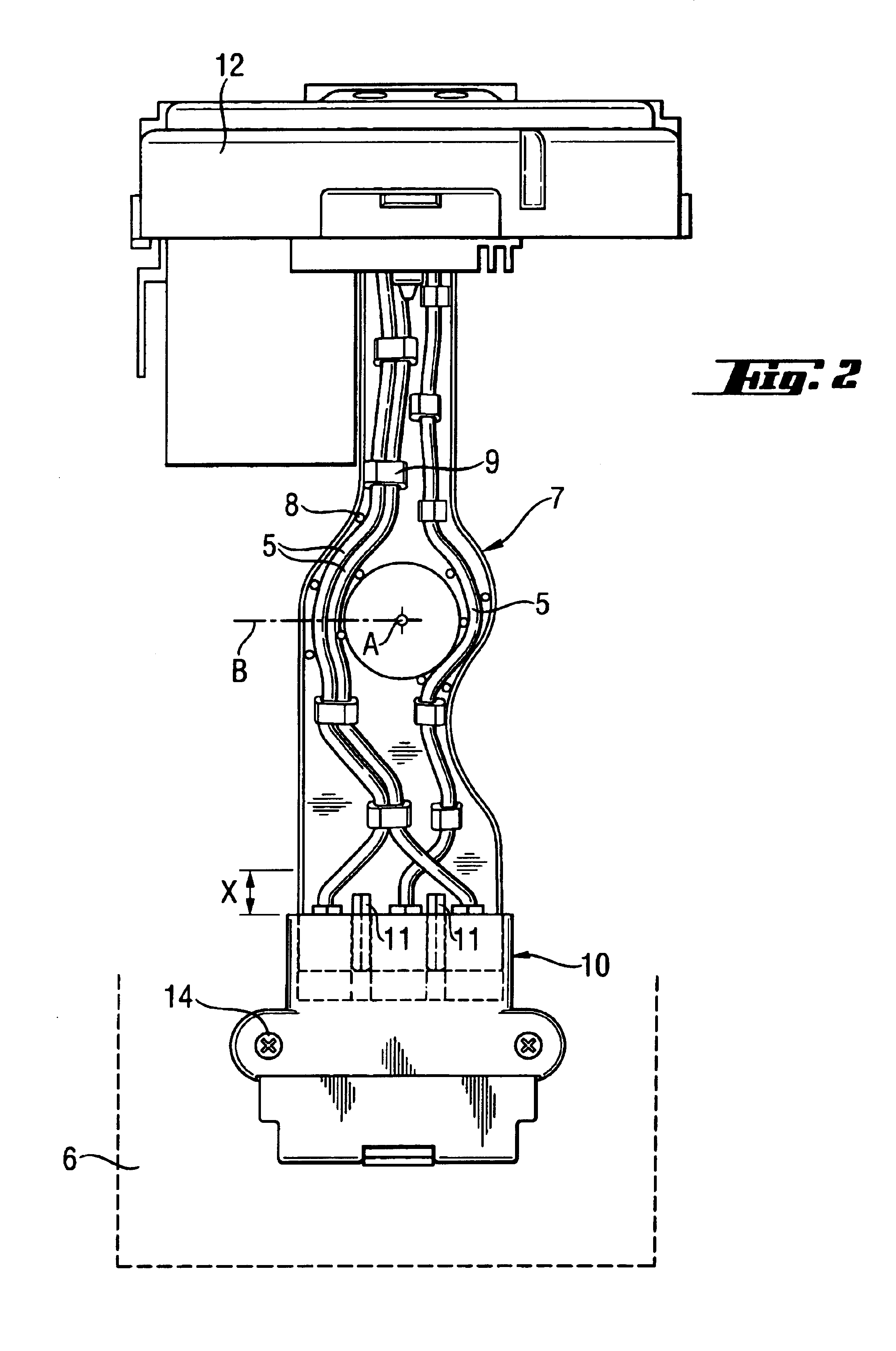
[0018]FIG. 1 shows a rotary and percussive electrical hand tool machine 1 having a housing 3 portable using a handle 2 and a striking mechanism module 4 relatively limited moveable along the striking axis A and connected vibration-damped thereto has a plurality of flexible, electrical lines 5, which connects the housing 3 and the striking mechanism module 4, which contain an electrical motor. The lines 5 are non-vibrationally attached to a wiring bridge 7 arranged transverse to the striking axis A, which is connected projecting and secure with an electronics module 12, in that is bonded to said latter via a casing mass 13. A plug connector 10 non-vibrationally mounted at the terminus of the wiring bridge 7 connected the electronics module 12 electrically with the electrical motor 6.

[0019]According to FIG. 2, the lines 5 are fastened non-vibrationally, in a defined bending flexible wiring bridge 7, arranged transverse to the striking axis A, relative to precisely one bending axis B o...


PUM

PropertyMeasurementUnit
frequencyaaaaaaaaaa
resistanceaaaaaaaaaa
flexibleaaaaaaaaaa

Abstract

A partially percussive electrical hand tool machine (1) having a portable housing (3), a striking mechanism module (4) connected, in a vibration-damped manner, to the housing (3) and having electrical lines (5) for electrical connection of the relatively moveable striking mechanism module (4) to the housing (3). The electrical lines (5) are non-vibrationally attached in a bending flexible wiring bridge (7) arranged transverse to the striking axis (A).

Description

BACKGROUND OF THE INVENTION[0001]The invention relates to an at least partially percussive electrical hand tool machine having a portable housing and a striking mechanism module vibrationally-damped thereto, in particular a chisel hammer.[0002]The pneumatic striking mechanism, in percussive electrical hand tool machines, usually driven by an electric motor and the interaction of the work piece with the percussive tool cause inertia-related vibrations that are transmitted through the housing to the operator, in the frequency range of 1 Hz to 100 Hz, which should be suppressed as much as possible. These type of striking mechanism modules that are vibration-damped using a spring to the housing are limited displaceable, approximately 10 mm, for producing a different pre-stressing along the striking axis and vibrate about this central position with an amplitude of a few millimeters.[0003]According to GB 215 4 497, an electrical hand tool machine has a striking mechanism module that is vi...

Claims


Application Information

Patent Timeline
Patent Type & Authority Patents(United States)
IPC IPC(8): B25D17/24B25D17/00B25F5/00
CPCB25D17/00B25D17/24B25F5/006B25D2222/54B25D2222/61B25D2250/041B25D2250/095
Inventor KRISTEN, FERDINANDMANSCHITZ, ERWIN
Owner HILTI AG
Learn More