
Vibratory venous and arterial oximetry sensor

Active Publication Date: 2005-09-20
THE UNITED STATES OF AMERICA AS REPRESENTED BY THE SECRETARY OF THE NAVY +1
View PDF39 Cites 175 Cited by
  • Summary
  • Abstract
  • Description
  • Claims
  • Application Information

AI Technical Summary

Problems solved by technology

In particular, this type of device is proficient at monitoring local muscular oxygen consumption rates as well as sudden changes in peripheral blood flow, as is known to occur in cases of sepsis and systemic shock.

Method used


Image

  • Vibratory venous and arterial oximetry sensor
  • Vibratory venous and arterial oximetry sensor
  • Vibratory venous and arterial oximetry sensor

Examples


Embodiment Construction

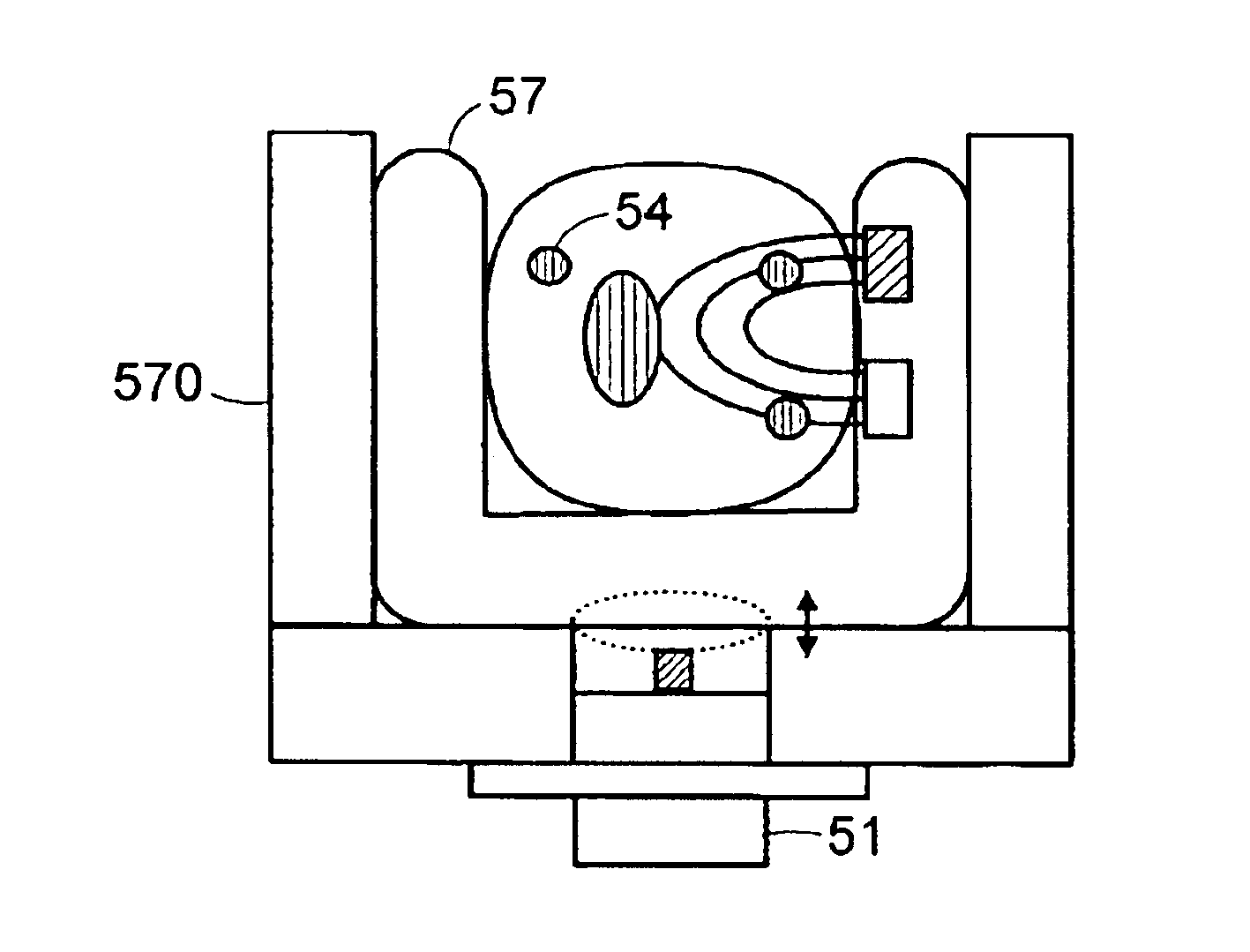
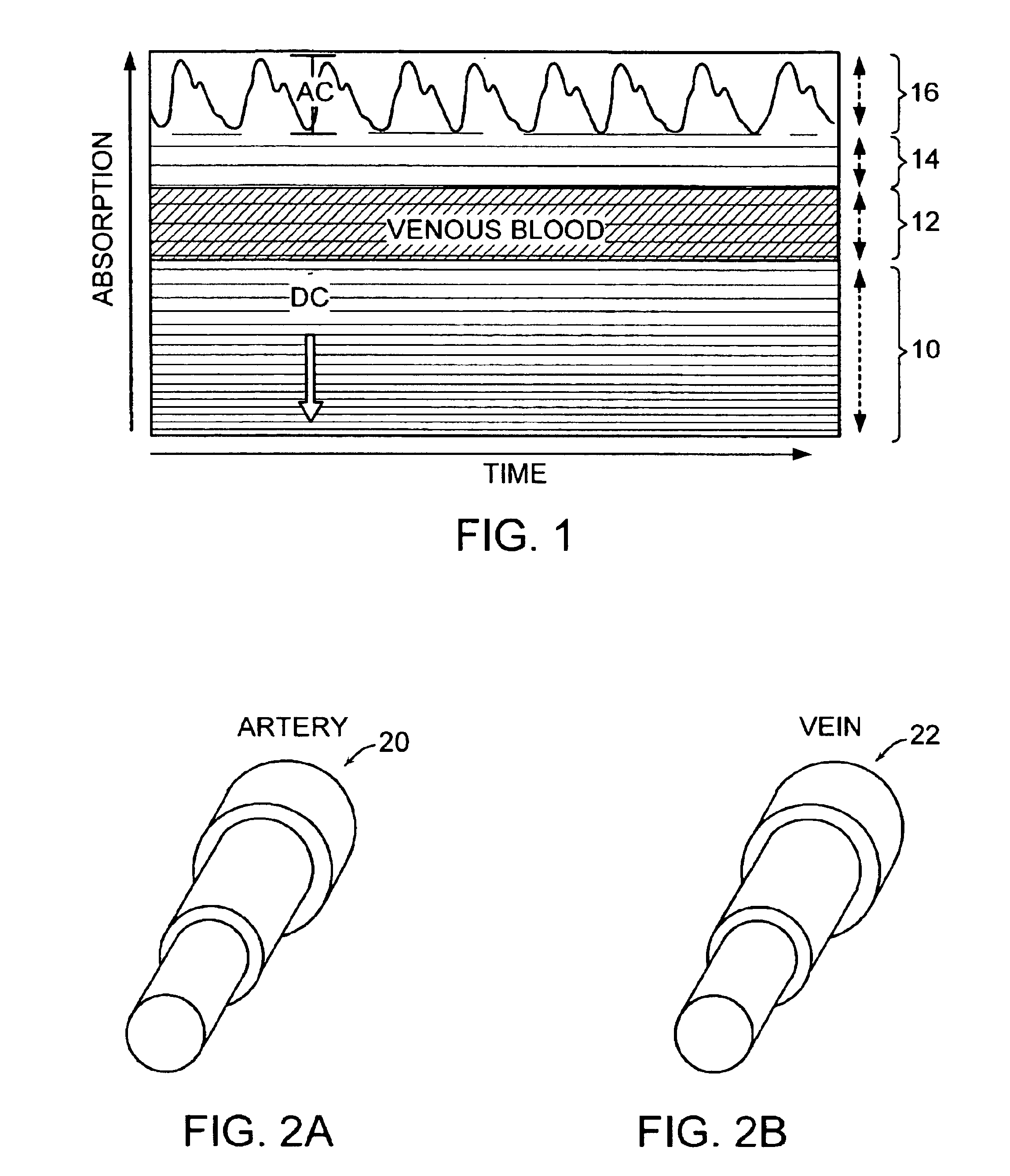
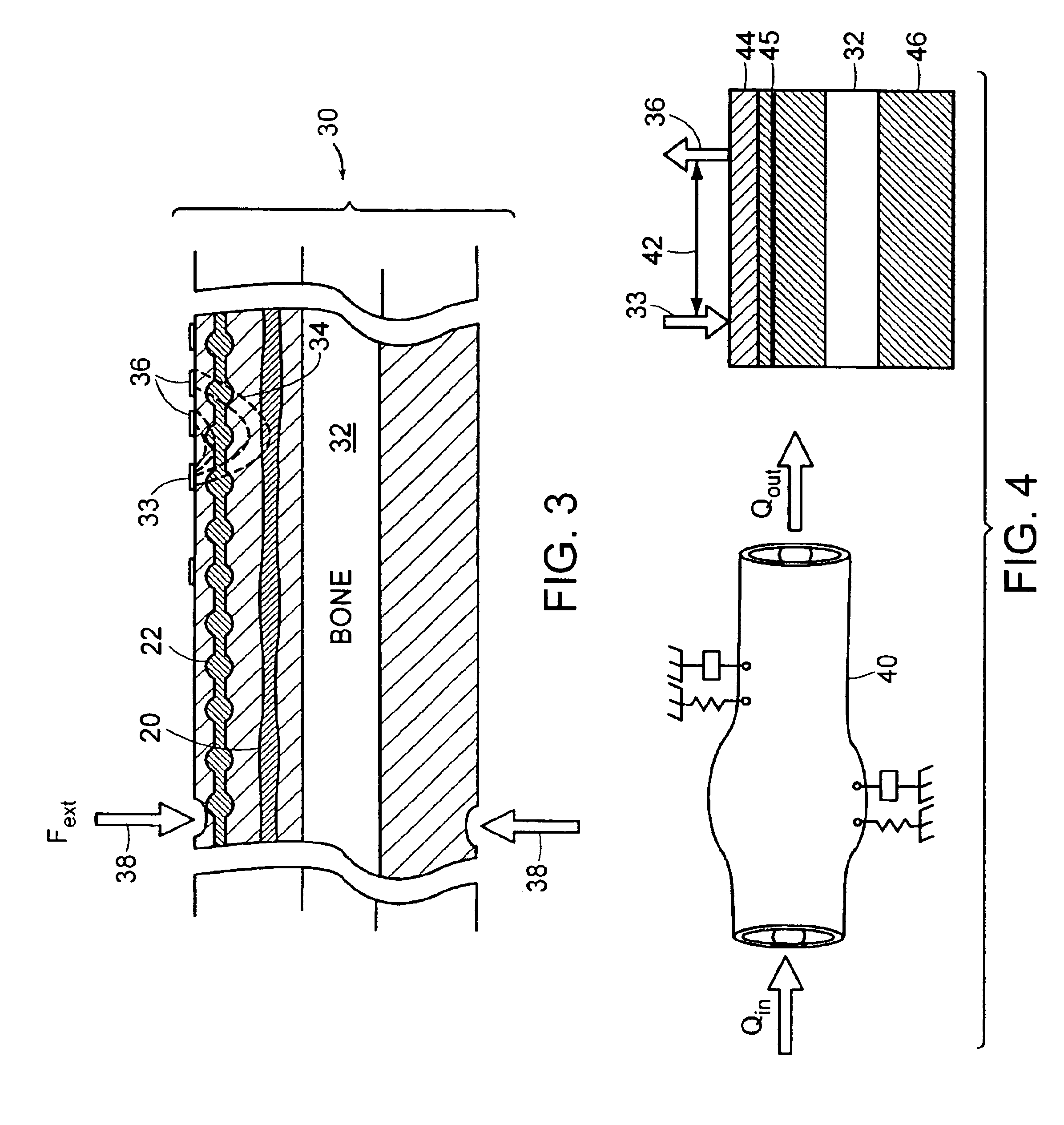
[0031]Advances in noninvasive cardiovascular monitoring have greatly enhanced our understanding of systemic metabolism and oxygen delivery kinetics. For example, near-infrared spectroscopy (NIRS) has been shown to be an extremely sensitive modality for studying local differences in muscle O2 consumption and delivery, as discussed in detail in Van Beekvelt et al, “Performance of near-infrared spectroscopy in measuring local O2 consumption and blood flow in skeletal muscle,”Journal of Applied Physiology, vol. 90, (2001), pp. 511-19, which is incorporated herein by reference. In addition to their high sensitivity, optically based monitoring designs are readily worn on the person and are capable of providing real-time information about the condition of the patient. These features afford such wearable, optical designs with a uniquely flexible applicability to the fields of both clinical health monitoring and enhanced fitness training.

[0032]Two primary considerations associated with venou...


PUM


Abstract

A method and an apparatus for distinguishing concentrations of blood constituents among distinct vascular components in situ. The method has steps of inducing periodic vibration, characterized by a frequency, in a limb of a person in such as manner as to selectively excite a resonant response in a specified blood vessel of the person, an artery or a vein, illuminating the limb of the person with a light source, and synchronously detecting a plethysmographic signal for discriminating response attributable to the specified blood vessel.

Description

[0001]The present application claims priority from U.S. Provisional Application, Ser. No. 60 / 433,570, filed Dec. 13, 2002, entitled “Vibratory Venous and Arterial Oximetry Sensor,” which Application is incorporated herein by reference.TECHNICAL FIELD[0002]The present invention relates to a device and method for monitoring the blood constituents of a patient and, more particularly, for continuously measuring the arterial and venous oxygen saturations of a patient using an external perturbation.BACKGROUND OF INVENTION[0003]Traditional pulse oximetry has been recommended as a standard of care for nearly all areas of the medical care. By measuring the relative absorptions of different wavelengths of light, transilluminating a given region of the body (normally the fingertip or the earlobe), important systemic and physiological information related to the cardiovascular system can be measured. Currently, arterial blood flow is used as the main source of information because it provides a u...

Claims


Application Information

Patent Timeline
IPC IPC(8): A61B5/00G01N21/17G01N21/31G01N21/35
CPCA61B5/0048A61B5/0084A61B5/1455A61B5/14551A61B5/14552A61B5/412G01N21/1717G01N21/314A61B5/0086A61B5/6824G01N21/359A61B5/0051
Inventor ASADA, HARUHIKO H.SHALTIS, PHILLIP
Owner THE UNITED STATES OF AMERICA AS REPRESENTED BY THE SECRETARY OF THE NAVY
Learn More