
Catheter for target specific drug delivery

a catheter and drug technology, applied in the field of medical catheters for target specific drug delivery, can solve the problems of inability to specifically target the patient site, lack of homogeneity of pore placement and pore number for fluid discharge, etc., and achieve the effect of accurate placemen

Inactive Publication Date: 2005-09-20
MEDTRONIC INC
View PDF33 Cites 88 Cited by
  • Summary
  • Abstract
  • Description
  • Claims
  • Application Information

AI Technical Summary

Benefits of technology

[0007]A new medical catheter has now been discovered that provides uniform distribution of therapeutic agents to a targeted patient site. Moreover, the medical catheter of the present invention has a unique structure that permits it to be accurately placed so that it can uniformly distribute therapeutic agents to the targeted patient site.
[0008]In a one embodiment of the present invention, the catheter has at least two distal ends, and a proximal end joined to the two distal ends via a connector, such as a “Y”, connector having three legs. Thus, the two distal ends and the proximal end are each located at a separate ends of an the legs of the connector. Preferably, restrictors are placed in each leg of the connector. A restrictor is a structure that provides a significant pressure drop when fluid flows through that structure. The restrictors of the present invention provide structure to balance the flow for a multiple catheter system. The restrictors can be made of any suitable material, e.g. a powder material such as sintered metal powder. In this embodiment, diffusers are placed at the distal ends. A diffuser is a structure that diffuses and delivers a therapeutic agent over a large surface area as opposed to a single point source. In this embodiment, the diffusers and restrictors, which are in each leg having a distal end, are separated from each other. Preferably, the diffuser is at the tip of each distal end, and the each restrictor is upstream of the distal end. This construction is particularly useful for delivery of drugs via multiple catheter ends. For example, drug delivery to the two different hemispheres of the brain may be achieved, and the present invention can deliver drugs to each hemisphere substantially equally because of the restrictor(s) upstream of the distal ends, rather than at the distal ends as are the diffusers. In this embodiment of the present invention the following benefits are obtained by separating the diffuser and the restrictor: (1) increase in design options for the catheter tip; (2) improved reliability of catheter tip that is implanted in the brain tissue; and (3) reduced need to test the restrictor structure for biostability.
[0009]In another embodiment of the present invention, a restrictor is placed upstream of the Y connector as well, so that there is a restrictor in all three legs of the catheter joined by the Y connector. This construction provides additional benefits. For example, having the restrictor upstream of the Y connector acts as a pre-filter, and thus removes any particulates prior to the Y connector. This pre-filter function reduces particulates to the restrictors downstream of the Y connector, thus reducing the potential for different pressure drops and flow rates through the restrictors downstream of the Y connector, and ultimately the flow rate of the delivered drug through the diffusers at the distal ends. In addition, this embodiment eliminates the possibility for insertion of a catheter where only one restrictor is downstream of the Y connector, and one restrictor is upstream of the Y connector.
[0013]Another objective of the present invention is to provide a catheter to diffuse a therapeutic agent over a larger surface area than from a single point source. This structure results in a decrease in fluid flux and reduces potential for damaging tissue near the infusion site. In order for equal or near equal bilateral drug delivery to occur, two distal ends are required since fluid delivered from one distal end to a target site at one hemisphere will not deliver fluid to the other hemisphere.

Problems solved by technology

A disadvantage of this assembly is that it results in a lack of homogeneity of pore placement and pore number for fluid discharge, which indicates a pore size of 2-20 microns.
While this design is capable of uniform fluid delivery to tissues adjacent to the permeable bag, a disadvantage of this assembly is its inability to be specifically targeted to a patient site due to the flexible distal bag.

Method used


Image

  • Catheter for target specific drug delivery
  • Catheter for target specific drug delivery
  • Catheter for target specific drug delivery

Examples


Embodiment Construction

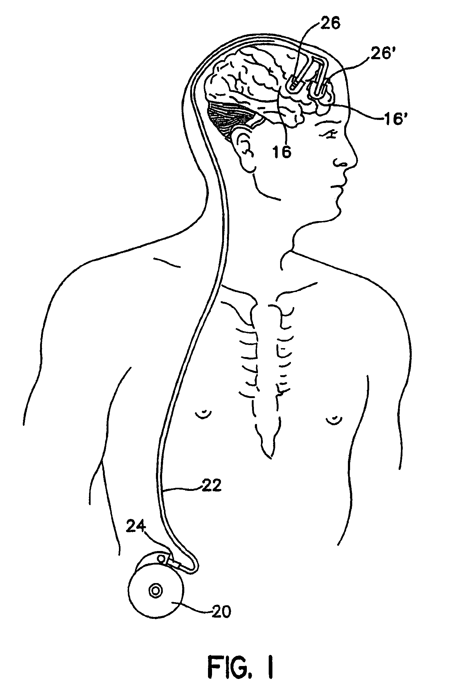
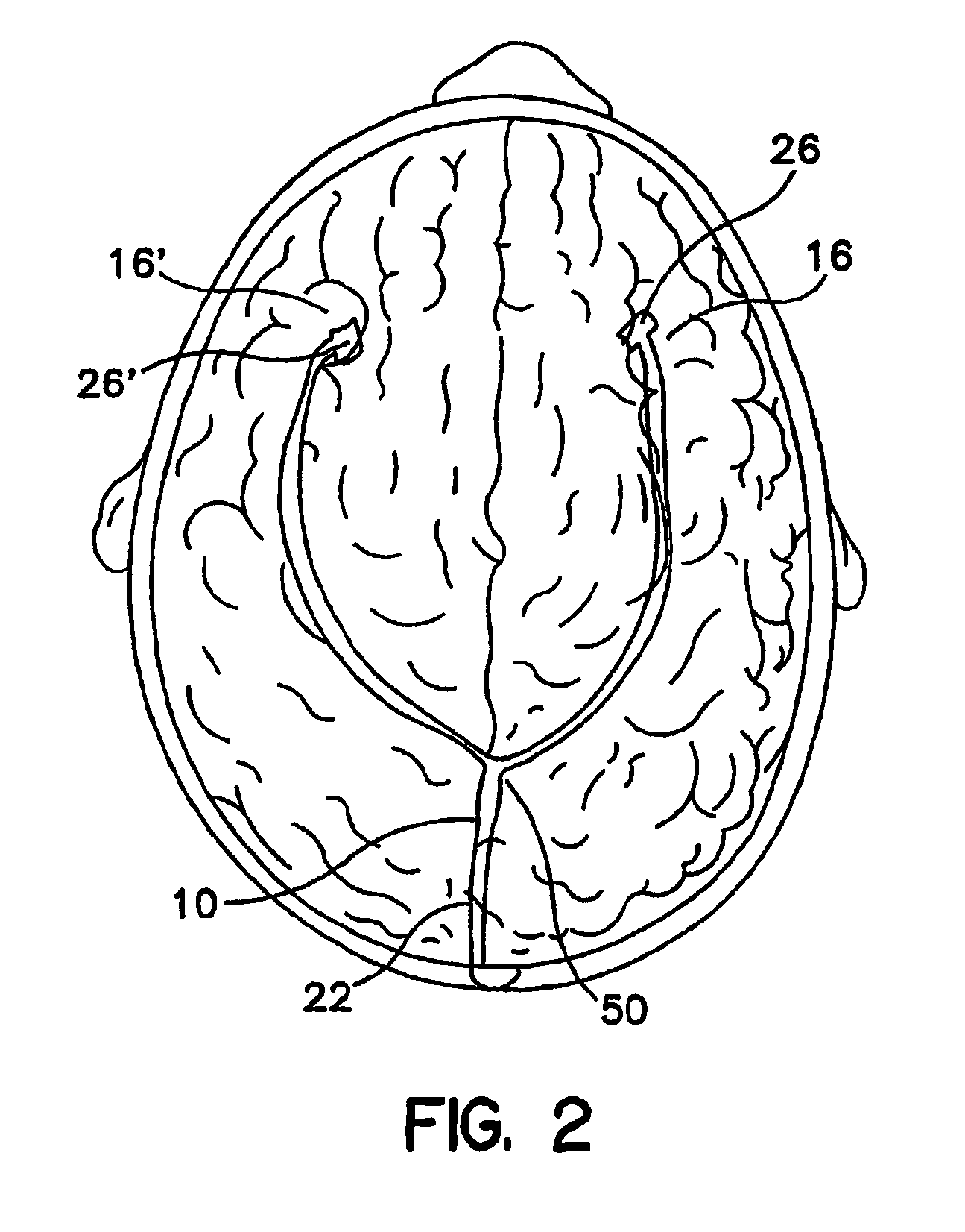
[0027]As shown in FIGS. 1 and 2, in an embodiment of the present invention, catheter 22 has a proximal end 24, and distal ends 26 and 26′. Distal ends 26 and 26′ are connected to catheter 22, which splits at a “Y” connector 50. Distal end 26 is positioned in the right anterior cerebral cortex 16, and distal end 26′ is positioned in the left anterior cerebral cortex 16′. Proximal end 24 is attached device 20, which can be an implantable infusion pump. While two distal ends are shown, the present invention can have one or more than two distal ends.

[0028]As further shown in the embodiment depicted in FIG. 2, catheter 22 has a catheter portion 10 downstream of device 20 and upstream of connector 50.

Combined Diffuser / Restrictor

[0029]As shown in FIG. 3A, where there is only one distal end 26, and there is no connector 50. Catheter portion 10 preferably comprises an elongated tubular wall 30 defining a central lumen 32. In this embodiment, catheter 22 begins at proximal end 24 and terminat...


PUM


Abstract

A medical catheter comprising a proximal end having an opening for fluid containing a therapeutic drug, a distal end, the distal end defining at least one opening, and a porous portion covering the opening defined by the distal end. In one embodiment, the medical catheter comprises a proximal end having an opening for fluid containing a therapeutic drug, at least two distal ends, the proximal end connected to the two distal ends with a connector, the distal ends each defining at least one opening, a diffuser covering the opening of each distal end, and a separate restrictor downstream of the connector and upstream of each distal end to provide substantially equal flow through each distal end. An additional restrictor can also be placed upstream of the connector. In another embodiment, a combination diffuser and restrictor covers the opening of each distal end. In one embodiment, the diffuser can define tubes that extend from the inside surface of the diffuser to the outside surface of the diffuser, to permit more equal drug flow through the tubes defined therein.

Description

CROSS-REFERENCE TO RELATED APPLICATION[0001]This application is a continuation-in-part of U.S. Ser. No. 09 / 540,444, filed Mar. 31, 2000 now U.S. Pat. No. 6,551,290.FIELD OF INVENTION[0002]This invention relates to medical catheters for target specific drug delivery.BACKGROUND OF THE INVENTION[0003]Medical therapies may require the targeting of the therapy to a targeted patient site to maximize the therapeutic benefit and / or minimizing adverse effects to other organs or tissues outside the targeted patient site.[0004]Huss & Reinhardt, U.S. Pat. No. 4,968,306 describes an elongated catheter assembly for intravascular delivery of intravenous therapeutic fluids. This assembly has a distal end having multiple pores which is sheathed by an outer proximal segment for variable exposure of delivery surface area by sliding the distal segment from the outer proximal sheath. A disadvantage of this assembly is that it results in a lack of homogeneity of pore placement and pore number for fluid d...

Claims


Application Information

Patent Timeline
IPC IPC(8): A61M25/00A61M5/142A61M27/00A61M5/168A61M39/02
CPCA61M5/14276A61M25/0069A61M5/16877A61M25/007A61M27/006A61M39/02A61M2025/0057
Inventor MORRIS, MARY M.HANKNER, DOUGLAS OWEN
Owner MEDTRONIC INC
Learn More