
Connector assembly for insulated concrete walls

a technology of connecting parts and concrete, which is applied in the direction of forms/shuttering/falseworks, forms/shuttering/falseworks, and building parts. it can solve the problems of projecting ties and difficulty for a single operator to reach from the edge of the insulation layer to position and interlock the two pieces of the connectors, so as to reduce the time and expense of constructing the walls, simplify the wall construction process, and reduce labor. the effect of labor

Inactive Publication Date: 2005-09-20
COMPOSITE TECH CO LLC
View PDF29 Cites 39 Cited by
  • Summary
  • Abstract
  • Description
  • Claims
  • Application Information

AI Technical Summary

Benefits of technology

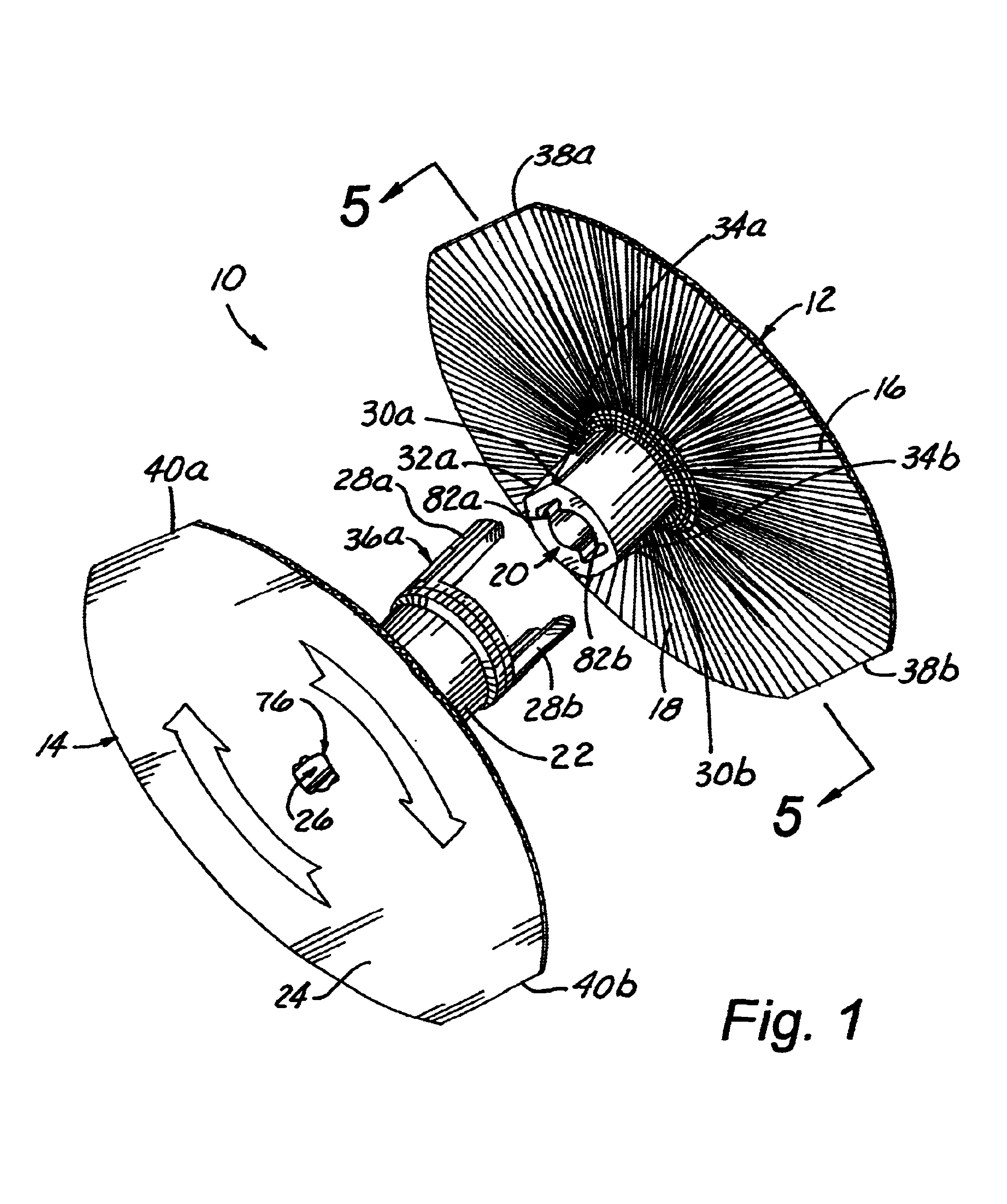
[0013]In a further embodiment, the cooperative engagement surfaces on the connector body and the tie also act to provide a stop or reference point for the preferred depth that the tie is to be inserted in the connector body. The stop or reference point will assure that the ties are all inserted in the connector bodies at a uniform depth. Uniform installation of the ties will assist in positioning the insulating layer at the desired location spaced from the two wall forms.
[0016]Another object of the invention is to provide a through-insulation connector assembly for use in constructing insulated concrete sandwich walls that is partially installed during manufacture to reduce the labor required in the wall construction process.
[0018]Yet another object of the invention is to provide a through-insulation connector assembly for use in constructing insulated concrete sandwich walls that reduces the time and expense of constructing the walls.

Problems solved by technology

The insulation layer is most commonly of a size, for example, four feet by eight feet, to make it difficult for a single operator to reach from the edge of the insulation layer to position and interlock the two pieces of the connectors.
A difficulty in this step is that one of the projecting ties may impinge on a portion of the grid and be directed or displaced off-center.

Method used


Image

  • Connector assembly for insulated concrete walls
  • Connector assembly for insulated concrete walls
  • Connector assembly for insulated concrete walls

Examples


Embodiment Construction

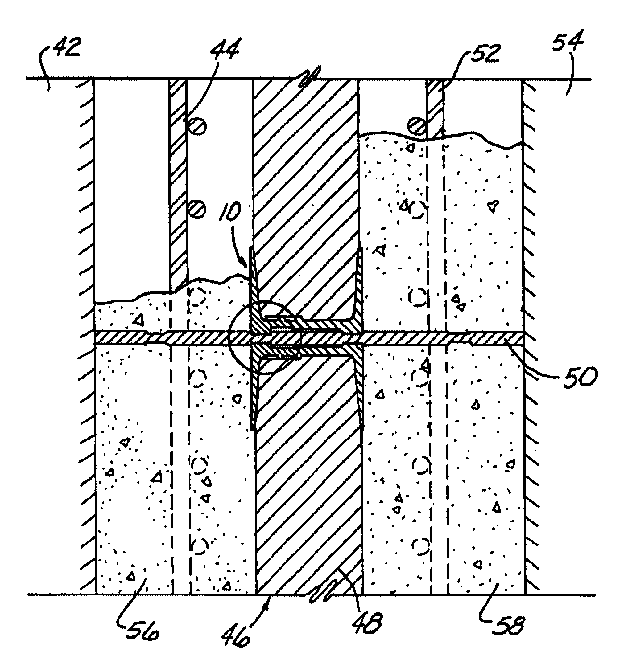
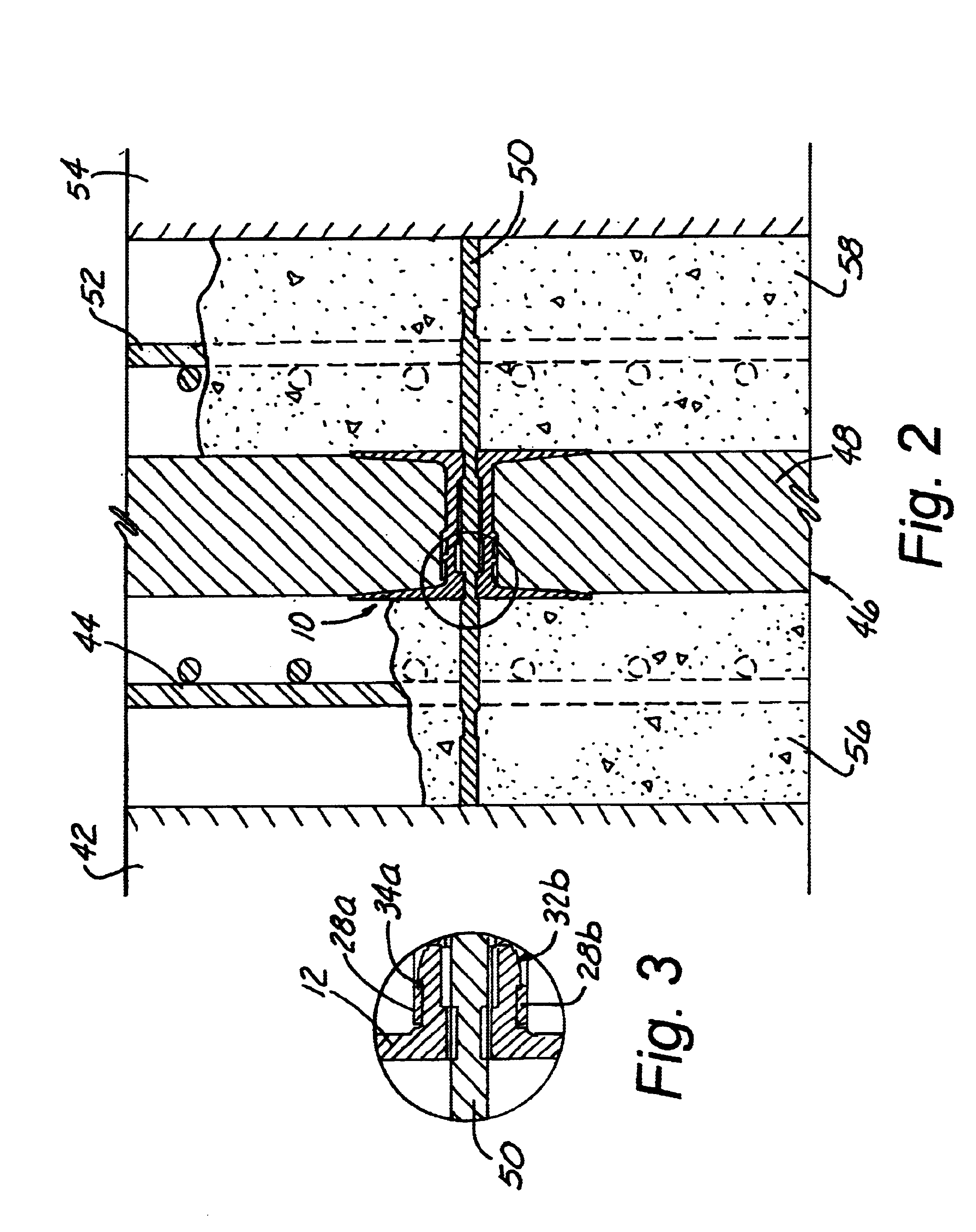
[0028]The present invention comprises a novel through-insulation connector assembly for use in the construction of insulated concrete sandwich wall and an improved method of constructing insulated concrete sandwich walls using the connector assembly. A preferred embodiment of the connector assembly includes a spool-shaped connector body comprised of two, interconnecting pieces and a tie that engages the connector body. The two pieces of the connector body are installed at the place of manufacture in a sheet of foam insulation that will be used as the insulation layer in the construction of an insulated concrete sandwich wall. The two pieces of the connector body each have a flange portion and a stem portion. The two pieces are axially aligned on opposite faces of the foam sheet with their stem portions facing the foam sheet. The two pieces are moved toward each other along their mutual axes until they are in contact engagement. The stem portions are dimensioned so that, upon mutual ...


PUM

PropertyMeasurementUnit
Flexibilityaaaaaaaaaa
Adhesivityaaaaaaaaaa

Abstract

A through-insulation connector assembly for use in the construction of insulated concrete sandwich wall. The connector assembly includes a spool-shaped connector body comprised of two, interconnecting pieces and a tie that engages the connector body. The two pieces of the connector body are installed at the place of manufacture in a sheet of foam insulation board that will be used as the insulation layer in the construction of an insulated concrete sandwich wall.

Description

[0001]This application claims priority to U.S. Provisional Application Ser. No. 60 / 234,492 filed Sep. 22, 2000.BACKGROUND OF THE INVENTION[0002]The invention relates generally to insulated concrete sandwich walls and methods of constructing such walls and, more particularly, to a two-piece connector that spans the insulation layer and engages a tie rod that passes through the insulation layer into the concrete layers on either side of the sandwiched insulation layer.[0003]Insulated concrete sandwich walls are well known in the art. Typically, a concrete sandwich wall panel is created by installing a layer of insulating material between two layers of concrete. In order to create a safe assembly capable of resisting handling and service imposed forces, the insulation layer must be penetrated by a connection system that ties the two layers of concrete together.[0004]Insulated concrete sandwich walls typically are constructed as horizontally-cast or vertically-cast assemblies. In both a...

Claims


Application Information

Patent Timeline
IPC IPC(8): E04G17/04E04G11/18E04C2/04E04G17/06E04G11/00E04C5/07
CPCE04C2/044E04C5/07E04G11/18E04G17/047E04G17/06E04C2002/047
Inventor LONG, SR., ROBERT T.
Owner COMPOSITE TECH CO LLC
Learn More