
Housing assembly for a self-inking stamp

a self-inking stamp and housing assembly technology, applied in the field of housing assembly for self-inking stamps, can solve the problems of spreading bacteria, unsightly and unattractive entire stamps, and inconvenient cleaning of entire self-inking stamps, and achieve the effect of restoring the entire self-inking stamp clean and nea

Inactive Publication Date: 2005-09-20
SHIH SHINY
View PDF9 Cites 57 Cited by
  • Summary
  • Abstract
  • Description
  • Claims
  • Application Information

AI Technical Summary

Benefits of technology

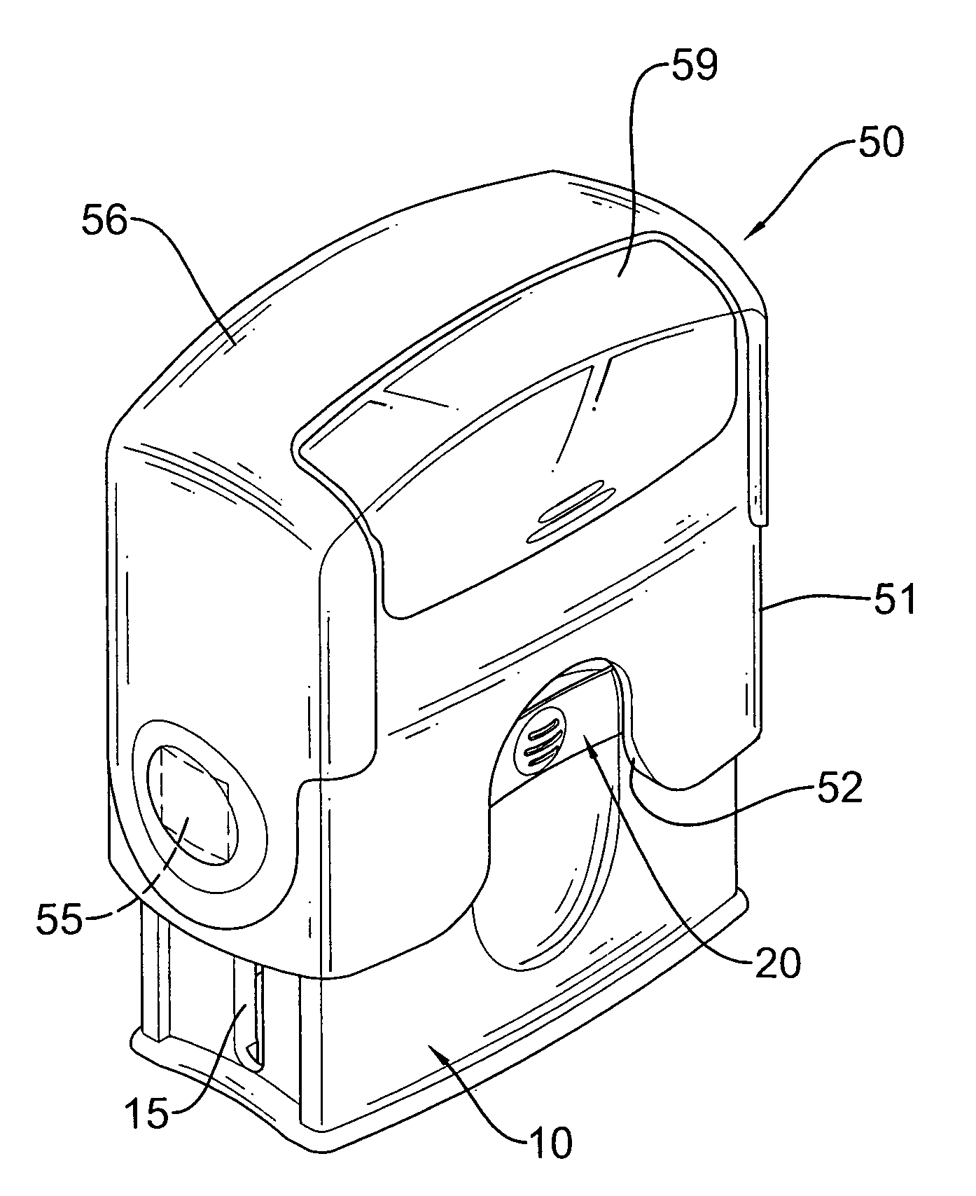
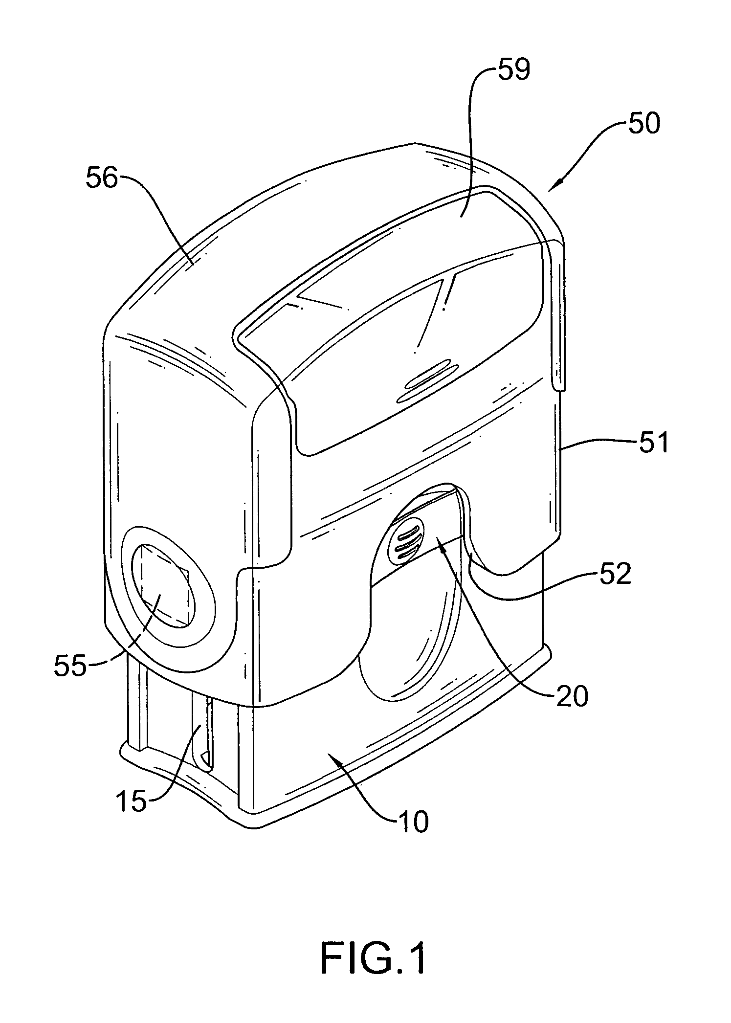
[0017]The housing assembly for a self-inking stamp in accordance with the present invention includes a movable case, two pressing keepers and a protective film. The movable case has two opposite sides and two keeper mounting holes respectively defined through the sides of the movable case and aligned with each other. The pressing keepers are respectively and movably mounted in the keeper mounting holes. The protective film is attached to the movable case and has two covering areas respectively aligned with and covering the pressing keepers. Consequently, the pressing keepers are completely enclosed and covered by the protective film, which will prevent gaps around the pressing keepers from being caulked or clogged with the contaminants as dust, skin oil or ink. In addition, the protective film will provide an improved touching feeling when a person holds the self-inking stamp.

Problems solved by technology

However, the entire stamp is not neat because of the extending pressing keepers (631).
The pressing keepers (631) extending solely at respective sides of the movable case (632) will cause the entire stamp to be unsightly and unattractive.
Furthermore, contaminants such as dust, skin oil or ink may caulk gaps around the pressing keepers (631), which will propagate bacteria.
Thus, the stamp will become dirty after a long-term use.

Method used


Image

  • Housing assembly for a self-inking stamp
  • Housing assembly for a self-inking stamp
  • Housing assembly for a self-inking stamp

Examples


Embodiment Construction

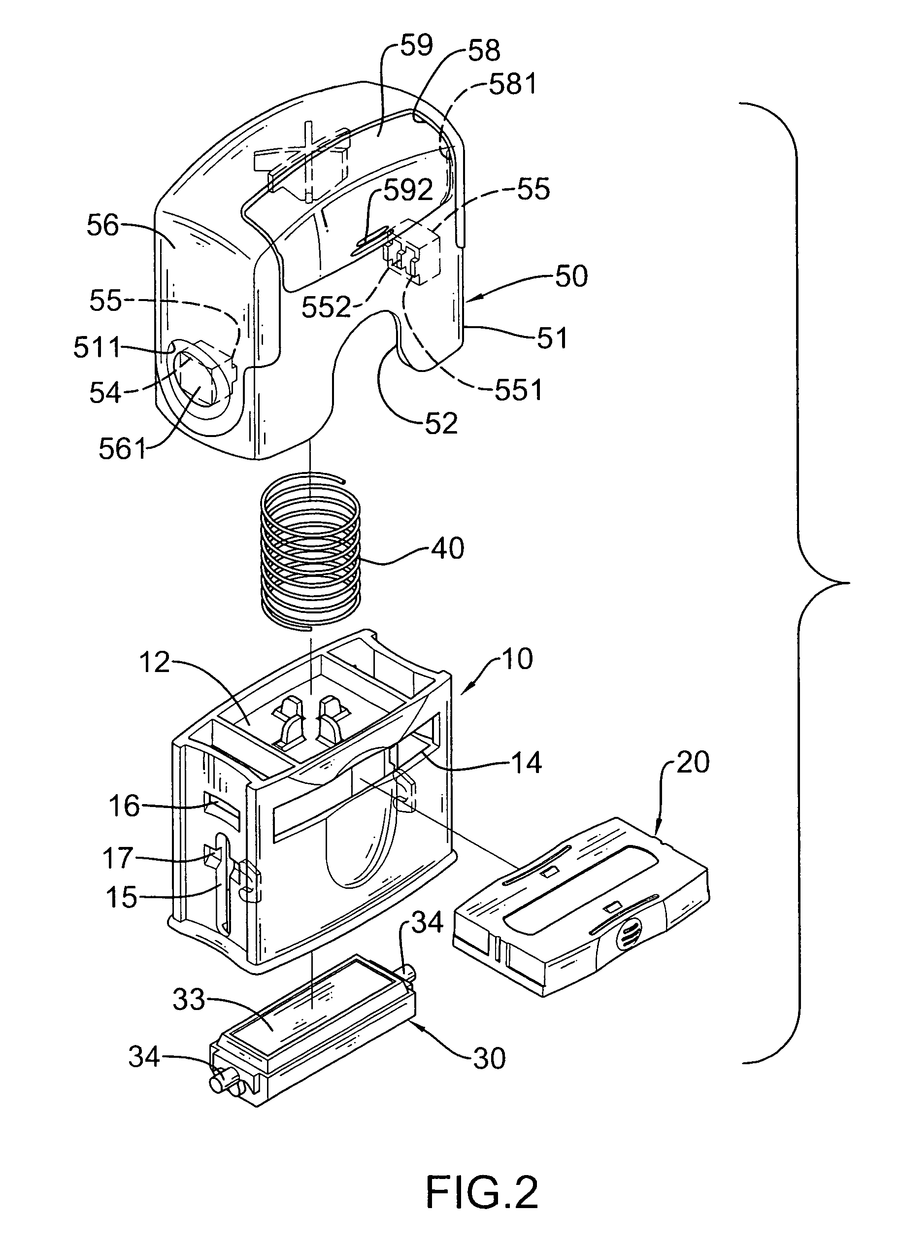
[0025]With reference to FIGS. 1 and 2, a self-inking stamp comprises a stationary case (10), an ink pad (20), a printing pad (30), a housing assembly (50) and a restitution element (40).

[0026]The stationary case (10) has a top (12), two opposite sides, two elongated slots (15), two upper detents (16), two lower detents (17) and an ink pad hole (14). The elongated slots (15) are completely defined through the sides of the stationary case (10) and are aligned with each other. The upper detents (16) are respectively defined in the sides over the corresponding elongated slots (15). The lower detents (17) are respectively defined in the sides of the stationary case (10) and overlap the corresponding elongated slots (15). The ink pad hole (14) is defined between the sides of the stationary case (10).

[0027]The printing pad (30) is slidably and rotatably mounted in the stationary case (10) along the elongated slots (15) and has two sliding studs (34). The sliding studs (34) are respectively...


PUM


Abstract

A housing assembly for a self-inking stamp includes a movable case, two pressing keepers and a protective film. The movable case has two opposite sides and two keeper mounting holes respectively defined through the sides of the movable case and aligned with each other. The pressing keepers are respectively and retractably mounted in the keeper mounting holes. The protective film is attached to the movable case and has two covering areas respectively aligned with and covering the pressing keepers. Consequently, the pressing keepers are completely enclosed and covered by the protective film, which will prevent gaps around the pressing keepers from being caulked or clogged with the contaminants as dust, skin oil or ink. In addition, the protective film will provide an improved touching feeling when a person holds the self-inking stamp.

Description

BACKGROUND OF THE INVENTION[0001]1. Field of the Invention[0002]The present invention relates to a housing assembly for a self-inking stamp, and more particularly to a housing assembly for a self-inking stamp wherein the housing assembly comprises an outside protective film to render the entire housing assembly clean and neat.[0003]2. Description of Related Art[0004]Self-inking stamps, such as business address stamps are convenient to print identical messages on different surfaces. With reference to FIG. 6, a conventional self-inking stamp comprises a stationary case (60), an ink pad (61), a printing pad (62), a housing assembly (63) and a restitution element (64).[0005]The stationary case (60) has a top, two opposite sides, a front, two elongated slots (601), two upper detents (602), two lower detents (603) and an ink pad hole (604). The elongated slots (601) are longitudinally defined in the respective sides. The upper detents (602) are respectively defined in the sides over the c...

Claims


Application Information

Patent Timeline
IPC IPC(8): B41J21/00B41K1/42B41K1/00
CPCB41K1/42
Inventor SHIH, SHINY
Owner SHIH SHINY
Learn More