
Gas distribution plate assembly for large area plasma enhanced chemical vapor deposition

a technology of gas distribution plate and plasma, which is applied in the direction of chemical vapor deposition coating, coating, coating process, etc., can solve the problems of high manufacturing cost, high frequency of drill bit breakage during hole formation, and scrapping of entire gas distribution pla

Inactive Publication Date: 2005-09-13
APPLIED MATERIALS INC
View PDF75 Cites 645 Cited by
  • Summary
  • Abstract
  • Description
  • Claims
  • Application Information

AI Technical Summary

Benefits of technology

[0011]Embodiments of a gas distribution plate for distributing gas in a processing chamber are provided. In one embodiment, a gas distribution plate includes a diffuser plate having a plurality of gas passages passing between an upstream side and a downstream side of the diffuser plate. At least one of the...

Problems solved by technology

Large gas distribution plates utilized for flat panel processing have a number of fabricating issues that result in high manufacturing costs.
For example, gas flow holes formed through the gas distribution plate are small in diameter relative to thickness of the gas distribution plate, for examples a 0.062 diameter hole through a 1.2 inch thick plate, resulting in a high frequency of drill bit breakage during hole formation.
Removal of broken drill bits is time consuming and may result in the entire gas distribution plate being scrapped.
Additionally, as the number of gas flow holes formed through the gas distribution plate is proportional to the size of the flat panel, the great number of holes formed in each plate disadvantageously contributes to a high probability of trouble during plate fabrication.
Moreover, the high number of holes coupled with the care required to minimize drill bit breakage results in long fabrication times, thereby elevating fabrication costs.
For example, if the gas flow holes formed through the gas distribution plate create too much backpressure, disassociated fluorine utilized to clean the plate has an increased propensity to recombine, disadvantageously diminishing cleaning effectiveness.

Method used


Image

  • Gas distribution plate assembly for large area plasma enhanced chemical vapor deposition
  • Gas distribution plate assembly for large area plasma enhanced chemical vapor deposition
  • Gas distribution plate assembly for large area plasma enhanced chemical vapor deposition

Examples


Embodiment Construction

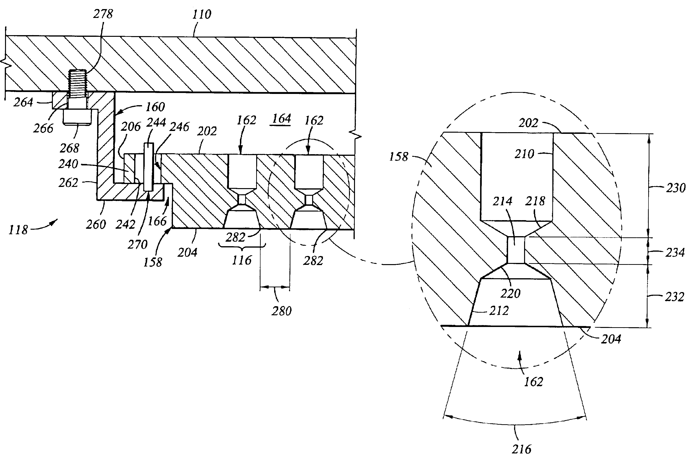
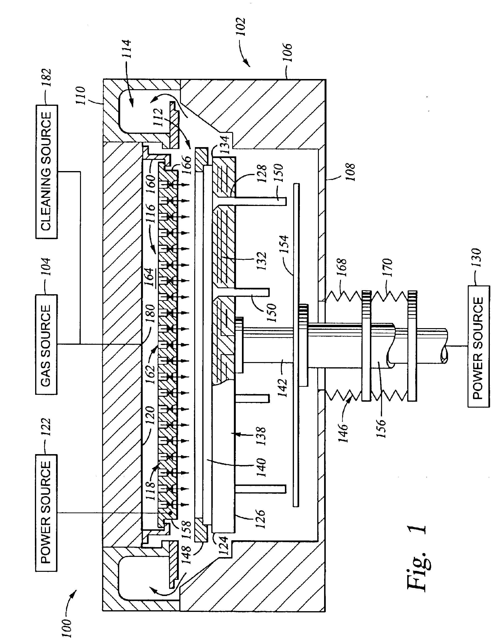
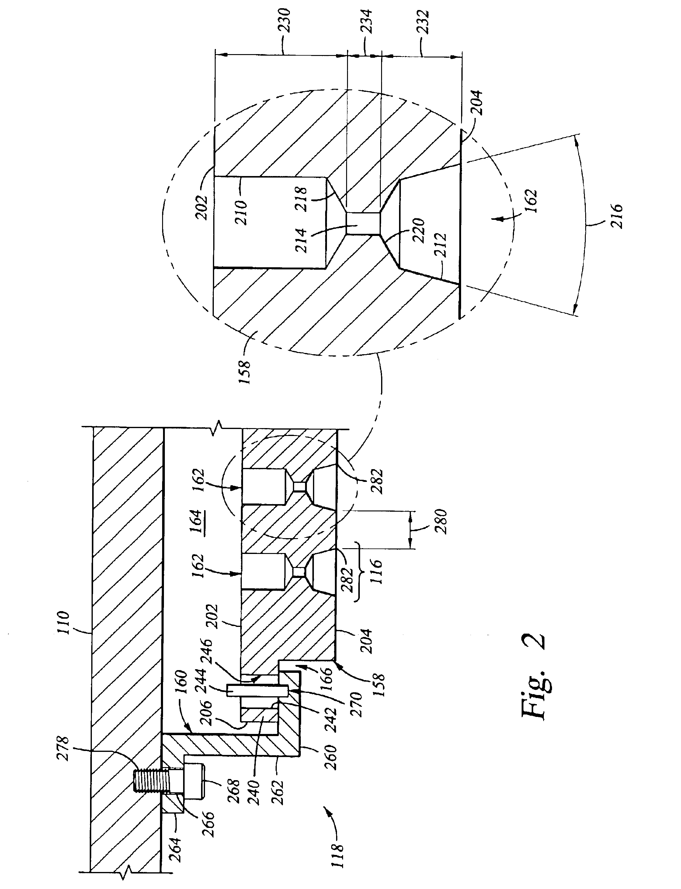
[0020]The invention generally provides a gas distribution plate assembly for providing gas delivery within a processing chamber. The invention is illustratively described below in reference to a plasma enhanced chemical vapor deposition system configured to process large area substrates, such as a plasma enhanced chemical vapor deposition (PECVD) system, available from AKT, a division of Applied Materials, Inc., Santa Clara, Calif. However, it should be understood that the invention has utility in other system configurations such as etch systems, other chemical vapor deposition systems and any other system in which distributing gas within a process chamber is desired, including those systems configured to process round substrates.

[0021]FIG. 1 is a cross sectional view of one embodiment of a plasma enhanced chemical vapor deposition system 100. The system 100 generally includes a processing chamber 102 coupled to a gas source 104. The processing chamber 102 has walls 106 and a bottom...


PUM

PropertyMeasurementUnit
Lengthaaaaaaaaaa
Thicknessaaaaaaaaaa
Angleaaaaaaaaaa

Abstract

Embodiments of a gas distribution plate for distributing gas in a processing chamber are provided. In one embodiment, a gas distribution plate includes a diffuser plate having a plurality of gas passages passing between an upstream side and a downstream side of the diffuser plate. At least one of the gas passages includes a first hole and a second hole coupled by an orifice hole. The first hole extends from the upstream side of the diffuser plate while the second hole extends from the downstream side. The orifice hole has a diameter less than the respective diameters of the first and second holes.

Description

BACKGROUND OF THE DISCLOSURE[0001]1. Field of the Invention[0002]Embodiments of the invention generally relate to a gas distribution plate assembly and method for distributing gas in a processing chamber.[0003]2. Description of the Background Art[0004]Liquid crystal displays or flat panels are commonly used for active matrix displays such as computer and television monitors. Generally, flat panels comprise two glass plates having a layer of liquid crystal material sandwiched therebetween. At least one of the glass plates includes at least one conductive film disposed thereon that is coupled to a power supply. Power supplied to the conductive film from the power supply changes the orientation of the crystal material, creating a pattern such as text or graphics seen on the display. One fabrication process frequently used to produce flat panels is plasma enhanced chemical vapor deposition (PECVD).[0005]Plasma enhanced chemical vapor deposition is generally employed to deposit thin film...

Claims


Application Information

Patent Timeline
IPC IPC(8): C23C16/50C23C16/509C23C16/44C23C16/455
CPCC23C16/45565C23C16/5096C23C16/511
Inventor CHOI, SOO YOUNGSHANG, QUANYUANGREENE, ROBERT I.HOU, LI
Owner APPLIED MATERIALS INC
Learn More