
Blood vessel catheter

Inactive Publication Date: 2005-09-13
RADIUS INT PARTNERSHIP
View PDF51 Cites 22 Cited by
  • Summary
  • Abstract
  • Description
  • Claims
  • Application Information

AI Technical Summary

Benefits of technology

[0011]A further object is to provide a bullet nose for a bolus that protects the leading edge of the catheter outflow or inflow port from rubbing against the vessel wall.
[0012]Another object is to provide a bullet nose bolus for a catheter that will not kink during insertion.
[0014]Another object is to provide a bullet nose bolus for a catheter that follows a guide wire through bends in a patent's vein and turns without causing increased resistance to passage through the vein.
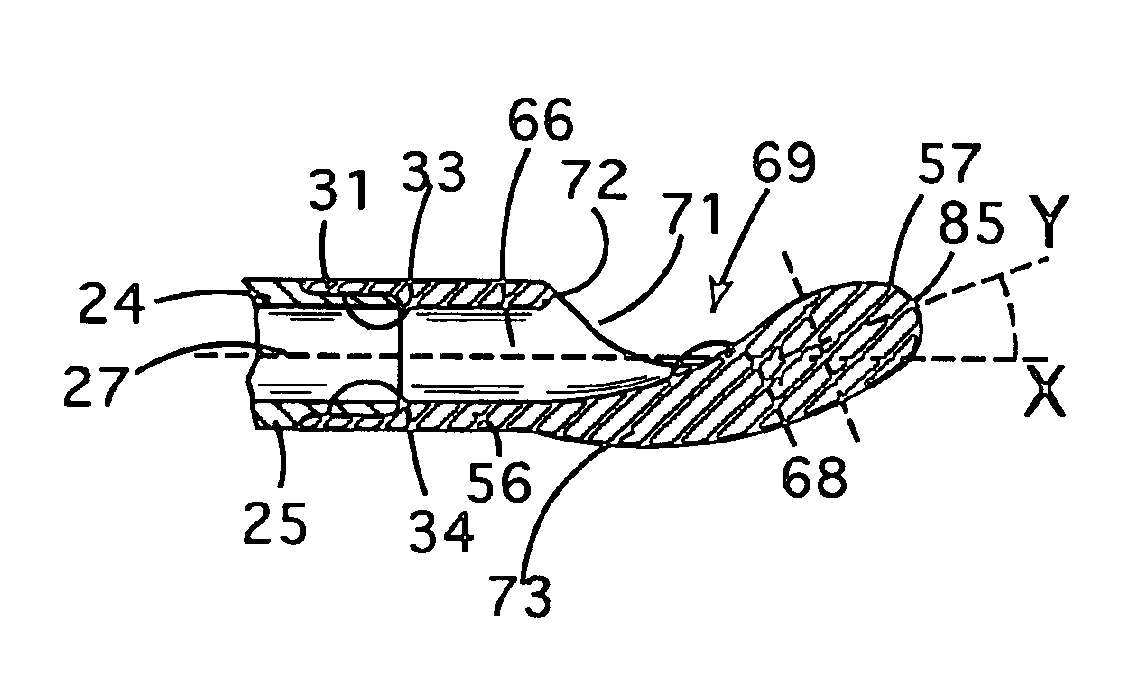
[0020]The nose section of the bolus is thus offset radially to the port side of the longitudinal axis of the bolus. This displacement results in a bolus configuration wherein a portion of the outermost periphery of the nose section is tangent to an imaginary cylinder containing the outer surface of the bolus passage section. This offset nose configuration serves to prevent the trailing edge of the port from abrading the vein wall.
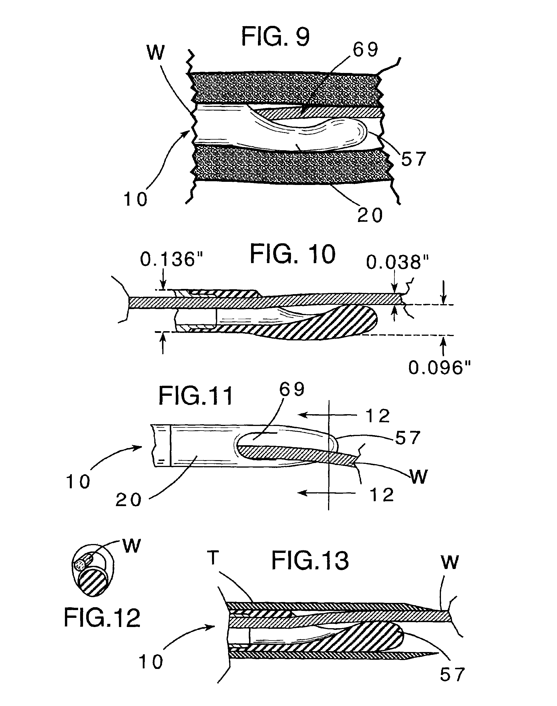
[0021]During insertion of the catheter into a patent's vein, however, the offset nose configuration serves another purpose. When a guide wire is passed through the bolus, the nose section flexes toward the longitudinal axis of the bolus to permit the wire to pass without forcing the nose section outside the larger tube profile, i.e., outside the imaginary cylinder in which the outer surface of the passage section lies. This makes insertion of the catheter much easier.

Problems solved by technology

Pliability can create a problem during insertion, however, because the catheters can kink when they meet resistance.
These catheters are more likely to cause damage to body tissue during insertion than bullet nose catheters, for example, because of their flat ends and side edges.
Open ended catheters are also more likely to damage tissue than bullet nose catheters while in-situ.
Nevertheless, the need for deep catheter insertion has heretofore made guide wire insertion of open-ended catheters the accepted procedure in spite of the disadvantage of their flat or blunt end design.
This approach has generally been found undesirable, however, because the hole in the bullet nose can later collect particulate matter and be a focal point for infection.

Method used


Image

  • Blood vessel catheter
  • Blood vessel catheter
  • Blood vessel catheter

Examples


Embodiment Construction

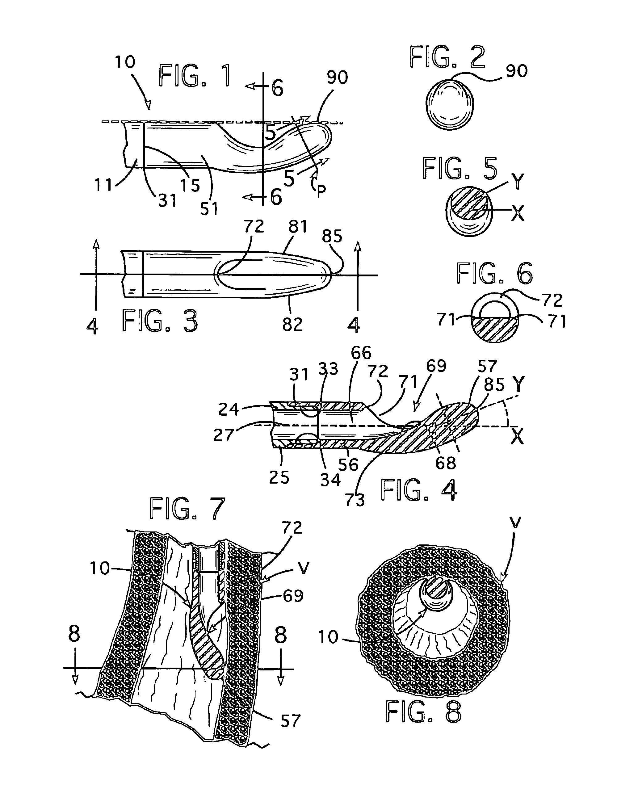
[0035]Referring now to the drawings, and particularly to FIGS. 1-3, a blood vessel catheter embodying features of the invention is seen generally at 10. The catheter 10 illustrated here includes a 10.5 French tube 11 which is preferably fabricated from silicone plastic. Although other plastics may be used, including polyurethane, the properties of silicone plastic have been found to be particularly advantageous in the present invention. Specifically, the MED-4770-A & B silicone product manufactured by the NuSil Technologies is preferred.

[0036]The 10.5 French catheter tube 11 has a distal end 15. Its proximal end, not shown, will have a conventional connector (not shown) fastened to it. The catheter tube 11 has a bolus 20 fastened to its distal end 15.

[0037]Referring additionally to FIGS. 4-6, the 10.5 French catheter tube 11 comprises a tubular plastic body 24 having an outside diameter (O.D.) of 0.136 inches. The body 24 includes a generally cylindrical wall 25 which defines a cyli...


PUM


Abstract

A blood vessel catheter including a catheter tube and a bolus having a bullet nose. The bolus includes a passage section with a side opening port. A nose section with a bullet nose has a smaller cross-section than the rest of the bolus and is offset from the axis of the passage section in the radial direction of the port. The bullet nose is rounded and unperforated.

Description

FIELD OF THE INVENTION[0001]This invention relates in general to medical catheters. It relates, more particularly, to blood vessel catheters.BACKGROUND OF THE INVENTION[0002]Blood vessel catheters are normally either venous catheters or arterial catheters. Venous catheters, in turn, usually come in several forms. The simplest are short peripheral catheters. Hemodialysis catheters comprise one form of central venous catheter and are normally placed in the superior vena cava.[0003]Blood vessel catheters of almost all types are pliable so that they do not damage body tissue when they are in-situ. Pliability can create a problem during insertion, however, because the catheters can kink when they meet resistance. Thus, there is often a need for a certain amount of stiffness so that the catheters can be directed within body vessels or cavities. There are currently two methods of providing this stiffness; stylets and guide wires.[0004]A stylet can be a single or a twisted wire with a blunt...

Claims


Application Information

Patent Timeline
IPC IPC(8): A61M25/00
CPCA61M25/0068A61M25/001A61M25/0069A61M25/008
Inventor QUINN, DAVID G.
Owner RADIUS INT PARTNERSHIP
Learn More