
Dual function terminal assembly and electric power apparatus incorporating the same

a terminal assembly and dual function technology, applied in the direction of electrical equipment, contacts, electrical and mechanical connections, etc., can solve the problems of poor electrical and mechanical connection, inconvenient and costly,

Active Publication Date: 2005-09-13
EATON INTELLIGENT POWER LTD
View PDF2 Cites 22 Cited by
  • Summary
  • Abstract
  • Description
  • Claims
  • Application Information

AI Technical Summary

Benefits of technology

The invention provides a terminal assembly that can be used for both a screw binding connection and a pressure plate connection, eliminating the need for two different types of terminals. The assembly includes a collar, a screw, and an insulating barrier. The collar is placed in the terminal cavity of an electrical power apparatus and has a through opening for the power conductor to pass through. The screw is then inserted into the collar and the insulating barrier is inserted into the through opening of the collar. The insulating barrier can be rotated between two positions to align with the power conductor in either a stranded wire or solid wire connection. The assembly also includes a compliant latch and latch surfaces in the molded casing of the power apparatus to secure the insulating barrier in either position. The technical effect of this invention is to provide a versatile terminal assembly that can be used for both screw binding and pressure plate connections, making it more convenient and efficient for users.

Problems solved by technology

If the same arrangement is used with stranded wire, the screw separates the wires clamping only a few, and breaking some, to make a poor electrical and mechanical connection.
With the presently available terminal assemblies, suppliers and users must maintain an inventory of both types of devices, which is inconvenient and costly.

Method used


Image

  • Dual function terminal assembly and electric power apparatus incorporating the same
  • Dual function terminal assembly and electric power apparatus incorporating the same
  • Dual function terminal assembly and electric power apparatus incorporating the same

Examples


Embodiment Construction

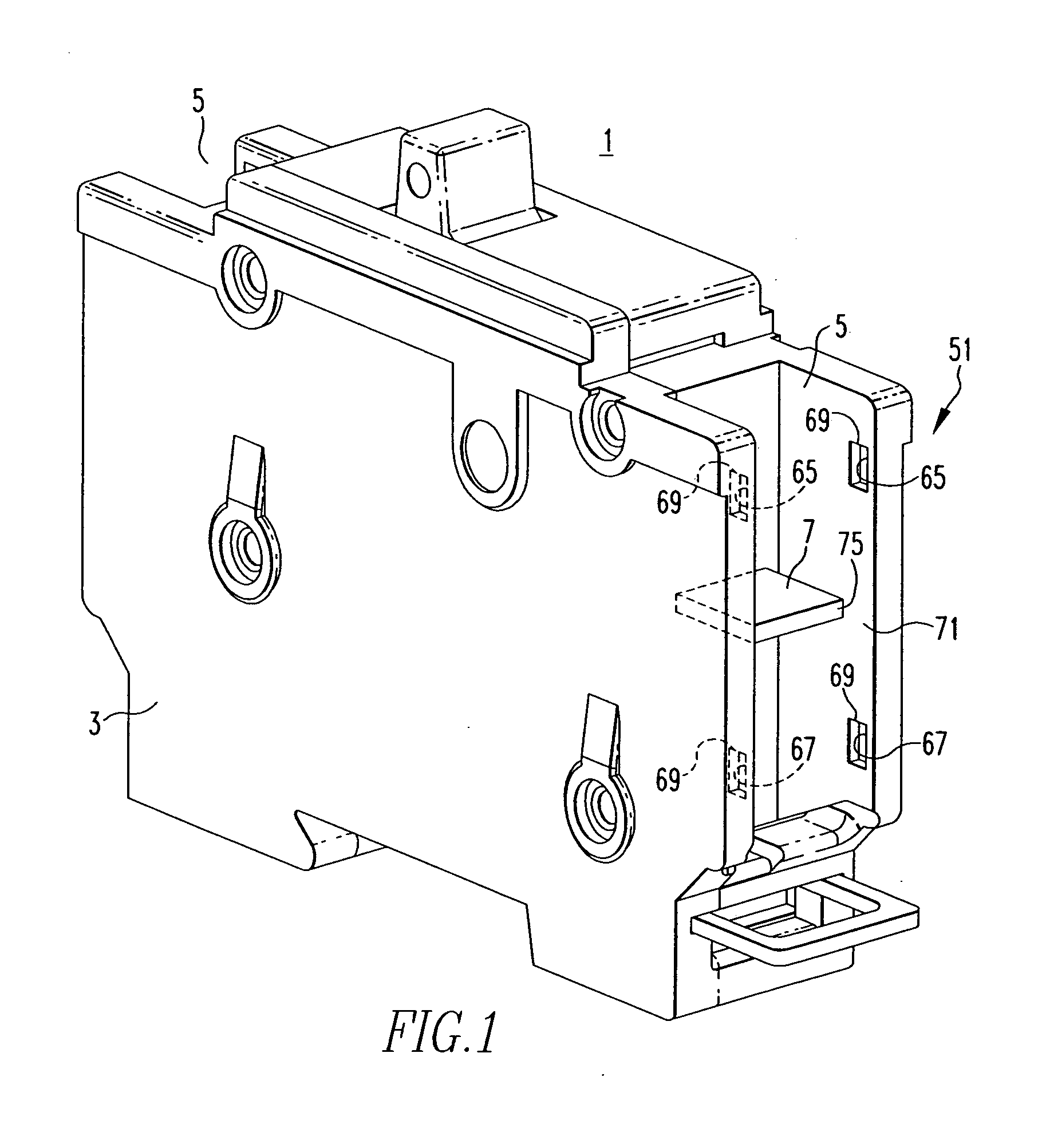
[0013]The invention will be described as applied to an electric power apparatus such as the single pole circuit breaker 1 illustrated in FIG. 1; however, it will become apparent that the invention can be readily applied to other types of electrical power apparatuses. This circuit breaker 1 has a molded casing 3 that incorporates terminal cavities 5 at each end into which power conductors 7, typically formed as a flat strap, extend (see also FIG. 3).

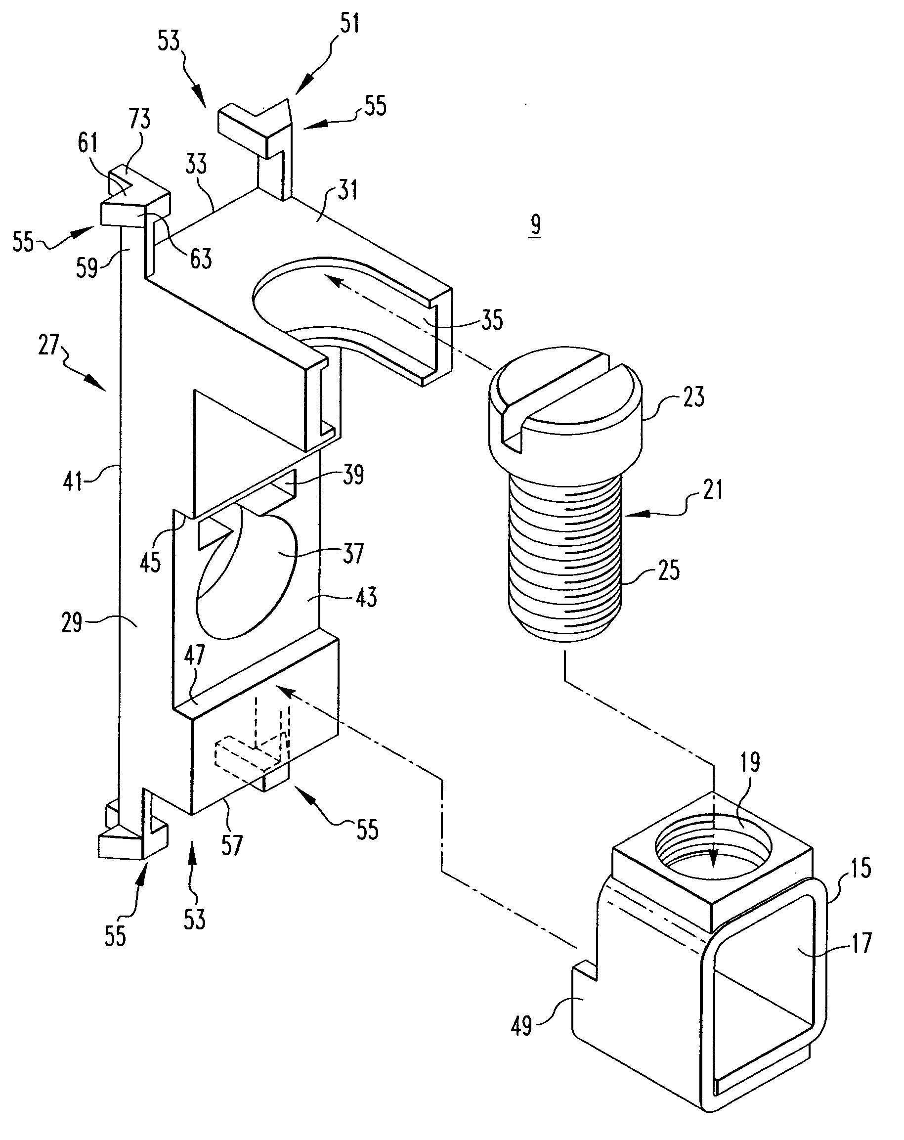
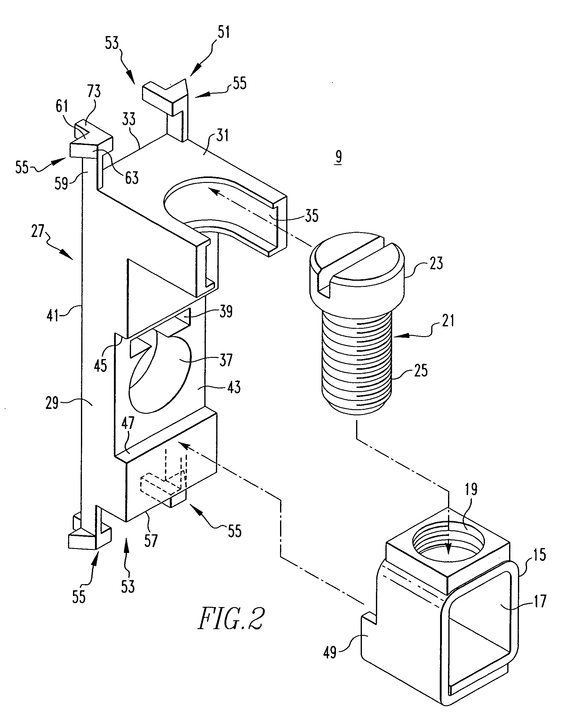
[0014]A feature of the invention is a terminal assembly 9 that interchangeably provides a pressure plate connection or a screw connection for connecting the power conductors 7 to external wiring that can be either a stranded wire 11 or a solid wire 13, as shown in FIG. 3.

[0015]Turning to FIG. 2, the terminal assembly 9 includes a collar 15 having a through opening 17 and a threaded cross opening 19 transverse to and extending to the through opening 17. A screw 21 having an enlarged head 23 and a threaded shaft 25 that screws into the thre...


PUM


Abstract

A terminal assembly can be alternatively used to make either a pressure plate or screw type connection for connecting stranded wire or solid wire, respectively, to a power conductor of electric power apparatus such as a circuit breaker. An electrically insulative barrier has an elongated member with a lateral extension at one end having a recess that captures the head of the screw of a terminal collar for the pressure plate connection. As the screw is tightened, the collar is drawn toward the power conductor to clamp the stranded wire between the collar and one side of the power conductor. With the elongated member turned end for end, the screw is free to clamp the solid wire against the other side of the power conductor. Pairs of integral compliant latches on the elongated member accommodate quick conversion between the two types of connections.

Description

BACKGROUND OF THE INVENTION[0001]1. Field of the Invention[0002]This invention relates to terminal assemblies for connecting a power conductor in electrical power apparatus to an external conductor, and particularly to such terminal assemblies that can be selectively applied in the field to provide either a screw binding connection or a pressure plate connection to the external conductor.[0003]2. Background Information[0004]Many types of electrical apparatuses have molded housings with external recesses into which power conductors within the apparatus extend for connection to an external conductor. It is common for the power conductor to be a flat strap of a conductive material such as copper. A terminal connector secures the external conductor to the strap. A common terminal connector comprises a collar having a through hole sized to slide onto the flat strap and through which the external conductor extends along the power conductor. A screw threaded through a transverse bore in th...

Claims


Application Information

Patent Timeline
Patent Type & Authority Patents(United States)
IPC IPC(8): H01R4/18H01R4/36H01R4/28H01R9/00H01R4/38H01R4/10H01R9/18H01H11/00H01H71/08
CPCH01H11/0031H01R4/36H01R4/38H01H71/08H01H2001/5861
Inventor LIAS, EDWARD E.WHIPPLE, MICHAEL J.
Owner EATON INTELLIGENT POWER LTD
Learn More