
Engine lubrication system

a technology for engine lubrication and lubrication pump, which is applied in the direction of engine lubrication, pressure lubrication with lubrication pump, mechanical apparatus, etc., can solve the problems of insufficient lubrication, the inability to replace the conventional mechanically driven pump with an electrically driven pump, and the inability to provide adequate lubrication, etc., to achieve the effect of reducing the size of the main pump

Active Publication Date: 2005-09-13
PIERBURG PUMP TECH UK
View PDF20 Cites 73 Cited by
  • Summary
  • Abstract
  • Description
  • Claims
  • Application Information

AI Technical Summary

Benefits of technology

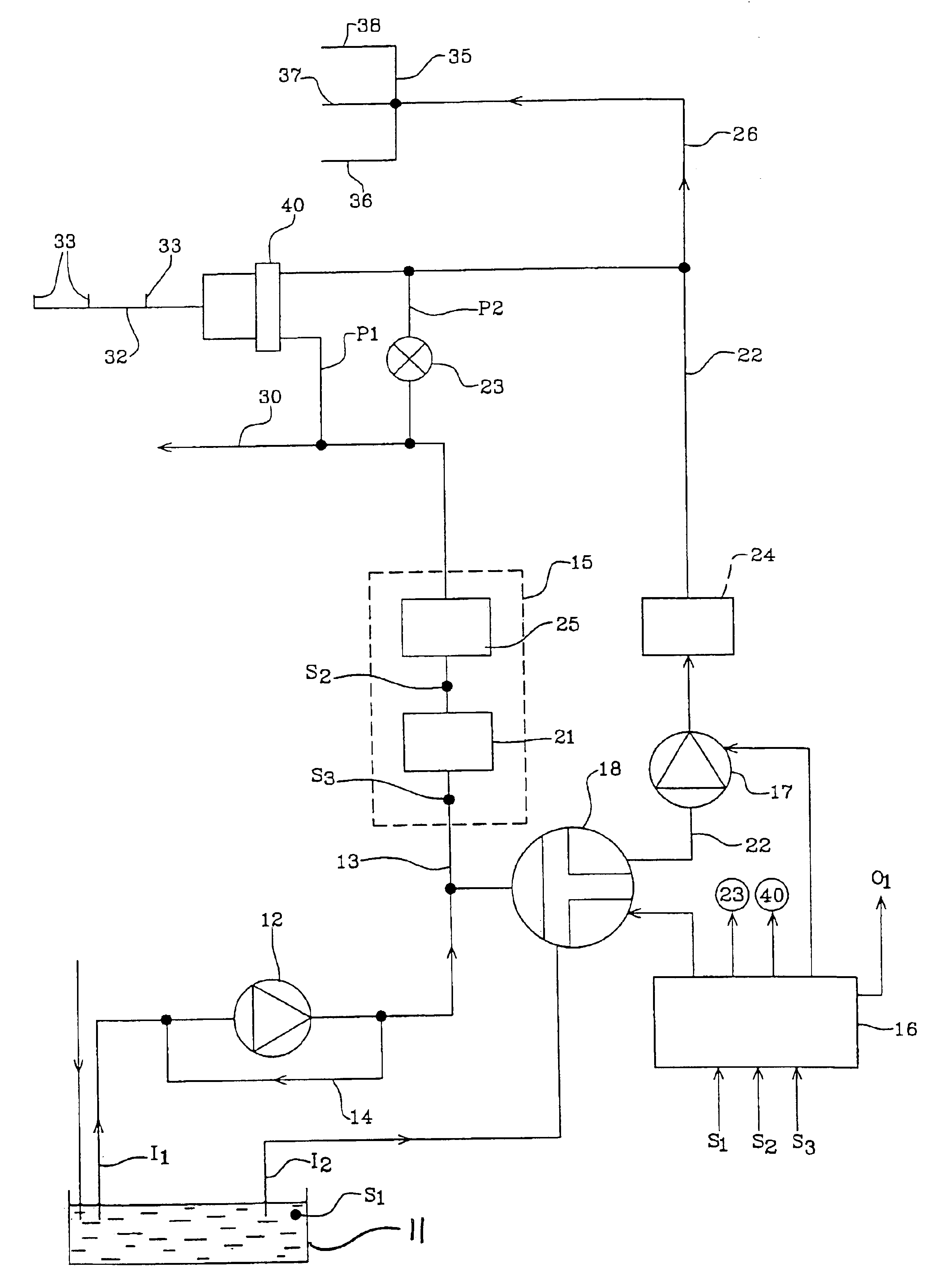
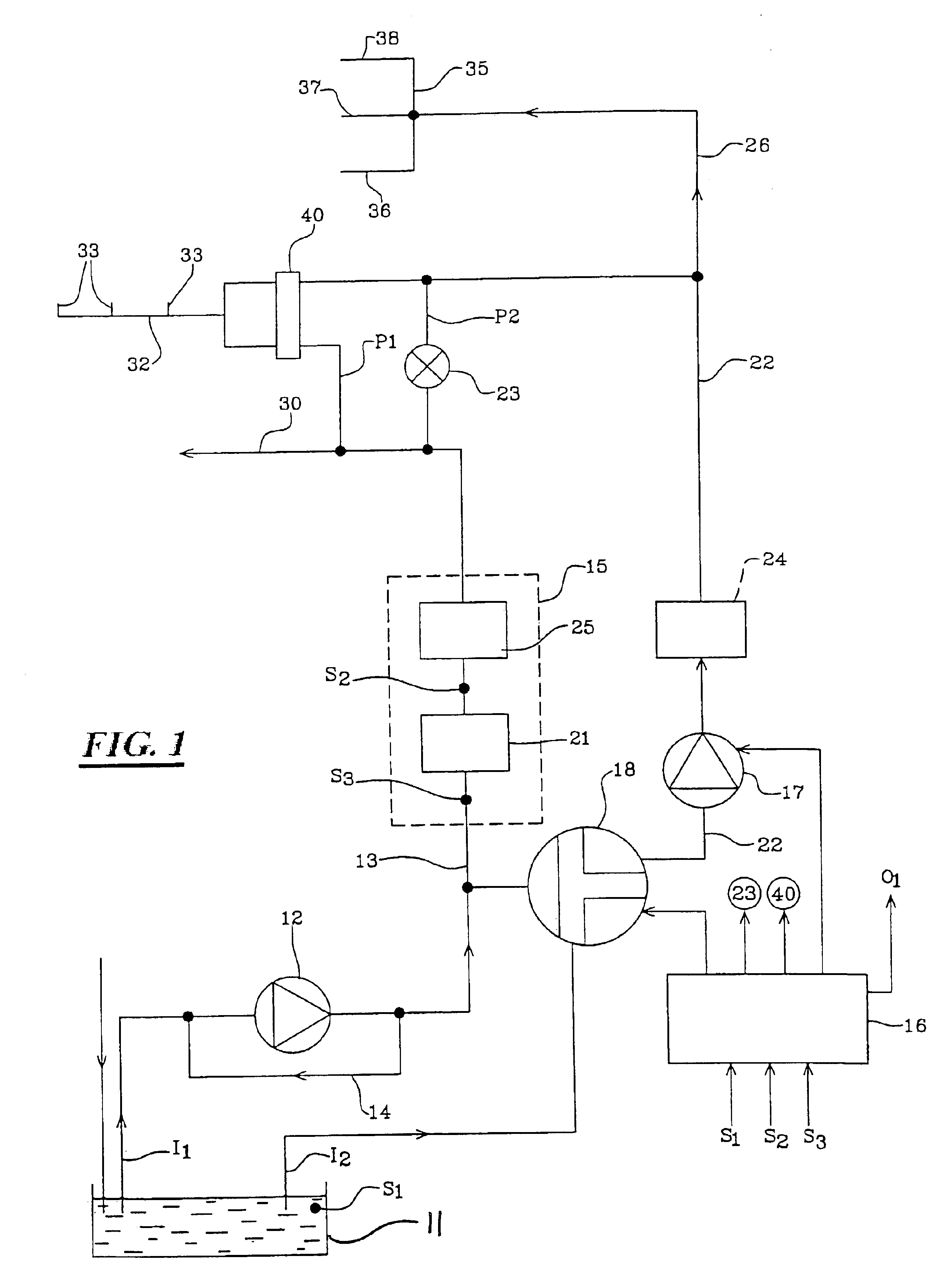
[0008]Thus by providing an auxiliary pump with a variable output, various advantages may be realised. Moreover, prior to engine start-up, the communication valve may be opened so that the auxiliary pump may be operated to pump lubricant to the main gallery via the communication passage to prime the lubrication positions fed by the main gallery, prior to engine startup.
[0009]The size of the main pump may be reduced compared to a similar system of similar rating because the main pump does not need to be able to satisfy the maximum possible demand for all engine speeds, as any deficiency may be made up by the auxiliary pump.
[0013]There may be a main lubricant inlet to the main pump and an auxiliary inlet to the auxiliary pump and a passage connecting the main feed line and the auxiliary inlet, with an isolating valve in the connecting passage. In one position the isolating valve may isolate the auxiliary pump inlet from the main feed line and in another position may provide communication between the main feed line and the auxiliary pump inlet, so that lubricant may be pumped by the main pump into the auxiliary feed line past the auxiliary pump.

Problems solved by technology

However at higher engine speeds, such mechanical pumps tend to pump lubricant in excess of that which is required for lubrication, making them inefficient, and in non-steady conditions, for example when the engine is operating at low speed under heavy load, it is possible that adequate lubrication will not be provided.
However a straight replacement of the conventional mechanically driven pump with an electrically driven pump only overcomes some of the deficiencies of using conventional mechanically driven pumps.

Method used


Image

  • Engine lubrication system
  • Engine lubrication system
  • Engine lubrication system

Examples


Embodiment Construction

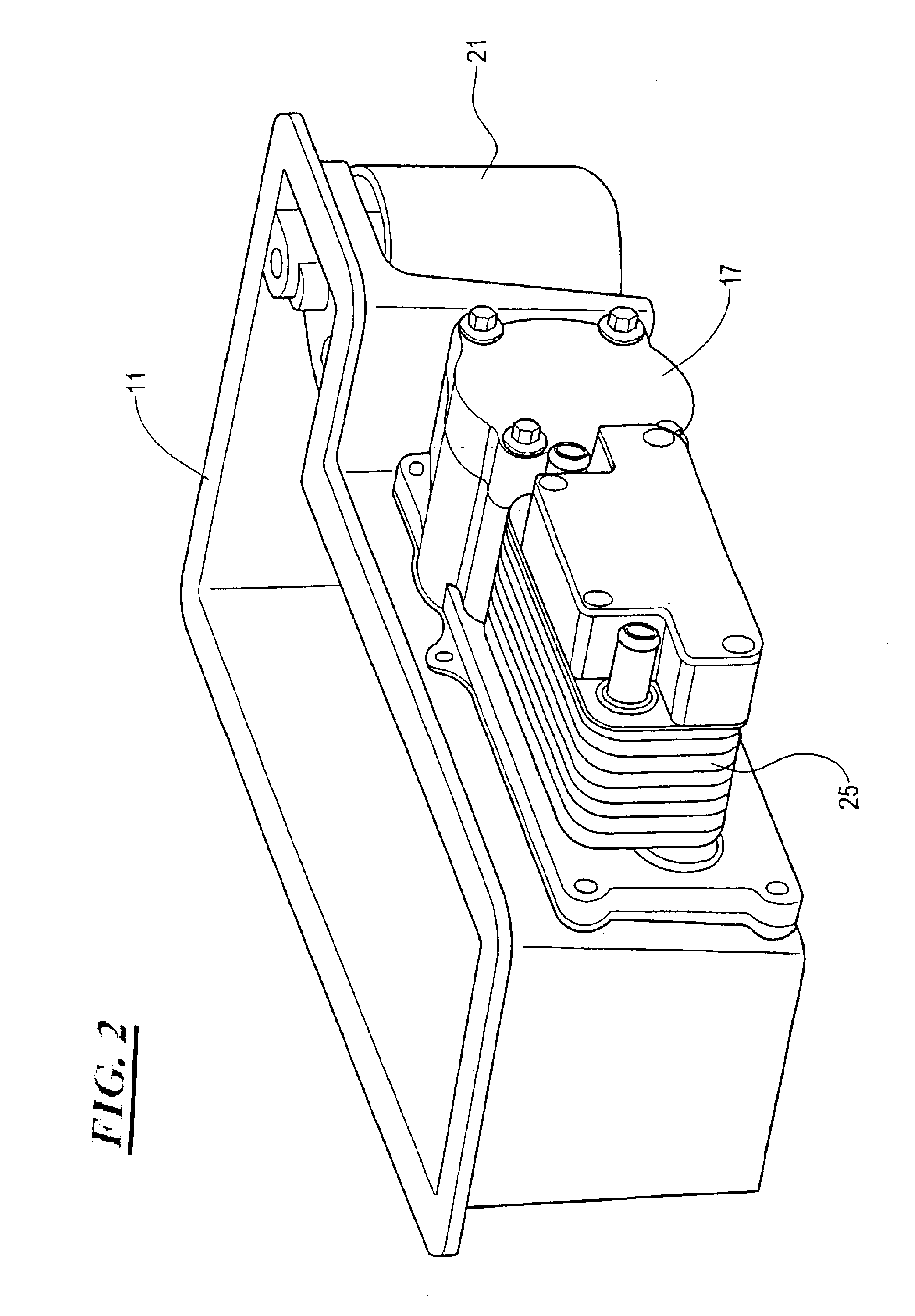
[0031]Referring to the drawing there is shown a lubrication system 10 for an engine. The system 10 includes a sump 11 for lubricant, and a main pump 12 for pumping lubricant from the sump 11 to lubrication positions in the engine.

[0032]The main pump 12 in this example is a pump with a linear output relative to engine speed at least over a normal engine speed operating range, and although the main pump 12 may be electrically driven, preferably the pump 12 is mechanically driven from an output member (e.g. crankshaft) of the engine.

[0033]The main pump 12 includes a by-pass 14 so that any excess lubricant the pump 12 is constrained to pump e.g. at higher engine speed by virtue of being mechanically coupled to the output member of the engine, can be returned to the sump 11 and thus not used for lubrication. Use of the by-pass 14 in this way represents an inefficiency of operation. A mechanically driven pump in a conventional arrangement must be able to pump enough lubricant at any engin...


PUM


Abstract

A lubrication system for an engine including a sump for lubricant, a main pump operable to pump lubricant to first lubrication positions within the engine, and an auxiliary lubricant pump also operable to pump lubricant to second lubrication positions within the engine and wherein the auxiliary pump is an electrically driven pump which is controlled by a system controller the output of the auxiliary pump being controlled according to engine operating conditions, the main pump in use, pumping lubricant to the first lubrication positions within the engine along a main lubricant feed line, and the auxiliary pump when operated pumping lubricant to the second lubrication positions within the engine along an auxiliary feed line, and wherein the main and auxiliary feed lines, are connected via a communication passage which includes a closeable communication valve, the communication valve when closed preventing the flow of lubricant from the auxiliary feed line to the first lubrication positions, and when open permitting the flow of lubricant from the auxiliary feed line to the first lubrication positions.

Description

ENGINE LUBRICATION SYSTEM[0001]This application claims priority to United Kingdom Patent Application No. 0211110.2 filed May 15, 2002, the entire disclosure of which is incorporated herein by reference.[0002]1. Background to the Invention[0003]This invention relates to an engine lubrication system and to a method of operating such a system.[0004]2. Description of the Prior Art[0005]Conventionally engine lubrication systems include a mechanically driven lubrication pump, the output of which is solely dependent upon the engine speed. In steady conditions and at lower engine speeds such mechanical pumps work well and efficiently. However at higher engine speeds, such mechanical pumps tend to pump lubricant in excess of that which is required for lubrication, making them inefficient, and in non-steady conditions, for example when the engine is operating at low speed under heavy load, it is possible that adequate lubrication will not be provided.[0006]Accordingly it has previously been p...

Claims


Application Information

Patent Timeline
IPC IPC(8): F01M1/02F01M1/00F01M1/12F01M1/16F01M5/00F01M11/02
CPCF01M1/02F01M2001/0215F01M2001/123F01M1/10F01M1/16F01M5/001F01M5/002F01M5/005
Inventor WILLIAMS, DAVID JOHNBLACK, DAVID THOMAS
Owner PIERBURG PUMP TECH UK
Learn More