Method for measuring the absolute steering angle of steering shaft for vehicle

a technology of absolute steering angle and steering shaft, which is applied in the direction of speed measurement using gyroscopic effects, instruments, surveying and navigation, etc., can solve the problems of difficult measurement of absolute steering angle of steering shaft using angle sensors only, and prior steering angle would not be used to measure relative changes, etc., to simplify calculation procedures and reduce measurement errors

Inactive Publication Date: 2005-09-06
HYUNDAI MOBIS CO LTD
View PDF5 Cites 36 Cited by
  • Summary
  • Abstract
  • Description
  • Claims
  • Application Information

AI Technical Summary

Benefits of technology

[0015]It is, therefore, an object of the present invention to provide a method for measuring an absolute steering angle of a steering shaft rotating by more than 360 degrees, to reduce measurement errors and to simplify a calculation procedure.
[0025]When the previous i-value is determined through the above procedure, the relative rotational angle Ψ′ of the first rotatable body is measured by using the angle sensor whose measurement range is Ω. To obtain a present i-value, 1 is added / subtracted to / from the previous i-value, based on a comparison result of a previous ΨM′ value to a present ΨM′ value. The reason for that is when the i-value is increased by as much as 1, the value of ΨM′ varies from Ω to 0, and when the i-value is decreased by as much as 1, the value of ΨM′ varies from 0 to Ω. That is to say, ΨM′ varies a lot before and after a variation of the i-value. The above procedure is useful not only for simplifying the calculation procedure, but also for freeing the influence of a measurement error included in θM′ upon the i-value.

Problems solved by technology

In general, measurement of an absolute steering angle of a steering shaft using an angle sensor only is known to be difficult because the measurement range is greater than 360°.
However, a prior steering angle would not be used to measure a relative change at present stage.
However, the above method poses a problem that ‘i−j’ has to be either 0 or 1 and should not be greater than 2 because a maximum value of Ψ−θ cannot be greater than Ω.

Method used


Image

  • Method for measuring the absolute steering angle of steering shaft for vehicle
  • Method for measuring the absolute steering angle of steering shaft for vehicle
  • Method for measuring the absolute steering angle of steering shaft for vehicle

Examples


Embodiment Construction

[0032]A preferred embodiment of the present invention will be described herein below with reference to the accompanying drawings. In the following description, well-known functions or constructions are not described in detail since they would obscure the invention in unnecessary detail.

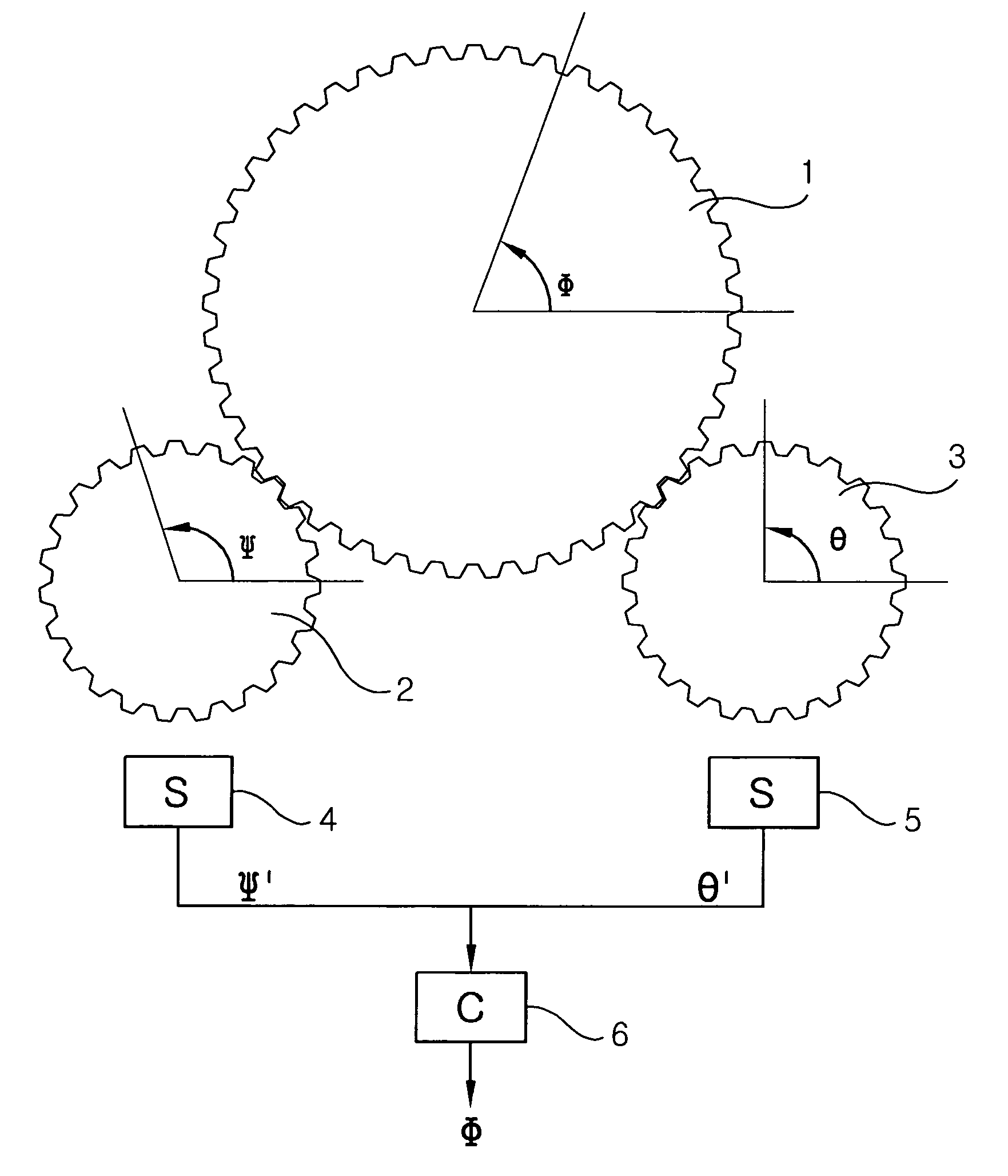
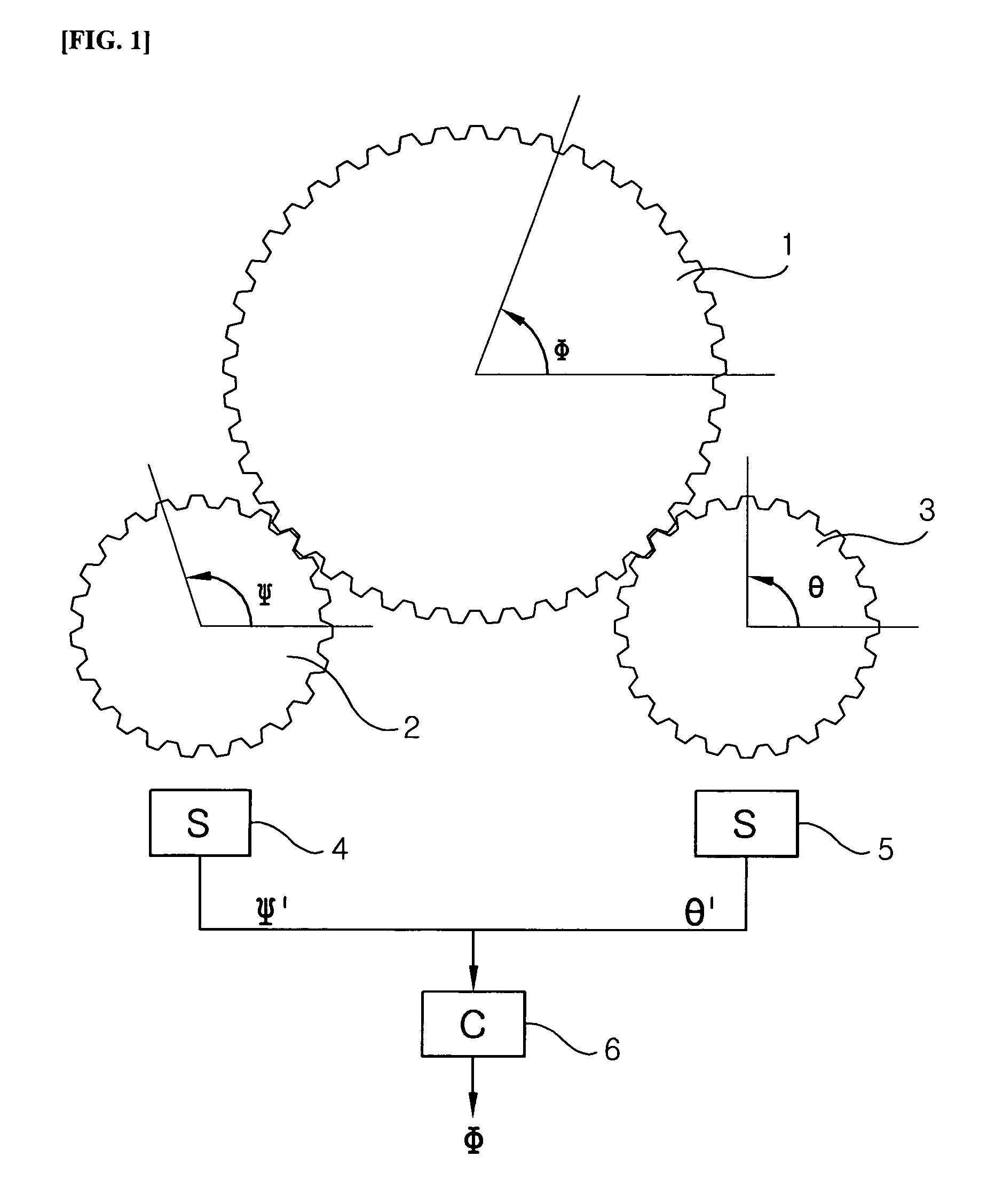
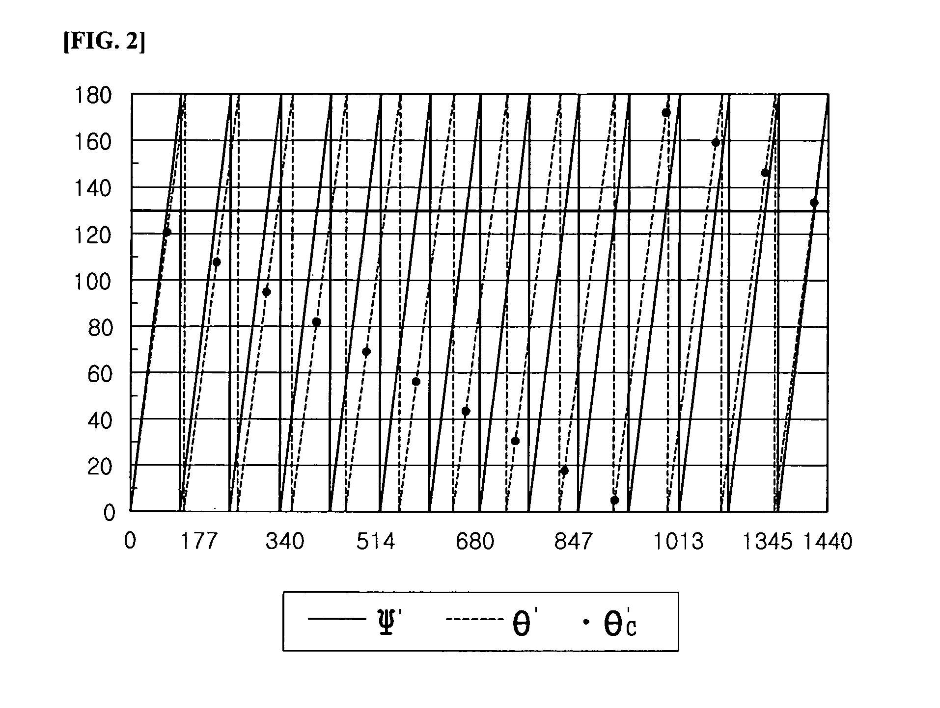
[0033]FIG. 1 shows a first rotatable body 2 and a second rotatable body 3 being engaged with a steering shaft 1, angle sensors 4 and 5 for measuring relative rotation angles Ψ′ and θ′ of the first and second rotatable bodies, and an operational circuit 6 for conducting a designated operation using Ψ′M and θ′M measurements provided by the sensors 4 and 5 and for outputting a resulting Φ. Here, a rotation ratio (r1) of the steering shaft to the first rotatable body is 7 / 4, and a rotation ratio (r2) of the steering shaft to the second rotatable body is 6.5 / 4 (the numbers of the teeth of the gears represented in FIG. 1 may not be correct). FIG. 2 graphically shows the relation between the relative rotatio...


PUM


Abstract

A method is provided for measuring an absolute steering angle Φ of a steering shaft for a vehicle, using a first rotatable body that rotates together with the steering shaft of the vehicle at a predetermined rotation ratio. The method includes obtaining a ΨM′ value by measuring a relative rotational angle Ψ′ of the first rotatable body using an angle sensor having a measurement range of Ω. The method also includes obtaining a present value for a frequency i-value of the first rotatable body by comparing the present ΨM′ value to a previous ΨM′ value. The method also includes obtaining a present value for a absolute steering angle Φ1 of the steering shaft from a present value for an absolute rotational angle Ψ of the first rotatable body by using the ΨM′ value and the present i-value.

Description

RELATED APPLICATIONS[0001]The present disclosure relates to subject matter contained in priority Korean Application No. 10-2003-0079321, filed on Nov. 11, 2003, which is herein expressly incorporated by reference in its entirety.BACKGROUND OF THE INVENTION[0002]1. Field of the Invention[0003]The present invention relates to a method for measuring an absolute steering angle of a steering shaft for a vehicle, and, more specifically, to a method for measuring an absolute steering angle of a steering shaft by using two rotatable bodies that rotate together with the steering shaft at a predetermined rotation ratio.[0004]2. Description of the Related Art[0005]In general, measurement of an absolute steering angle of a steering shaft using an angle sensor only is known to be difficult because the measurement range is greater than 360°.[0006]Also the steering angle of the steering shaft should be immediately measured following start-up of a vehicle, regardless of an initial angular position....

Claims


Application Information

Patent Timeline
Patent Type & Authority Patents(United States)
IPC IPC(8): G01C9/00G06F15/00G01B21/22G01D5/245
CPCG01D5/2452G01B21/22
Inventor LEE, JONG-HWAKIM, WAN-SUBKANG, CHANG-WON
Owner HYUNDAI MOBIS CO LTD
Why Eureka
Try Eureka