
To a combined fingerprint acquisition and control device

a control device and fingerprint technology, applied in the field of computer input devices, can solve the problem of more difficult to determine the rotation of the finger with respect to the scanner

Inactive Publication Date: 2005-09-06
SYNAPTICS INC
View PDF5 Cites 212 Cited by
  • Summary
  • Abstract
  • Description
  • Claims
  • Application Information

AI Technical Summary

Benefits of technology

The present invention provides better methods for calculating parameters and using them. Specifically, it provides an improved method for calculating rotational information for a fingerprint. The scanner is imaging the interface between the finger and the scanner, and the image will vary depending on the position and rotation of the fingertip. It is easier to determine which area of the image displays a fingerprint, but it is more difficult to determine the rotation of the finger with respect to the scanner.

Problems solved by technology

It is simple to work out where the fingertip is in contact with the scanner, by looking at which area of the image displays a fingerprint, but it is more difficult to determine the rotation of the finger with respect to the scanner.

Method used


Image

  • To a combined fingerprint acquisition and control device
  • To a combined fingerprint acquisition and control device
  • To a combined fingerprint acquisition and control device

Examples


Embodiment Construction

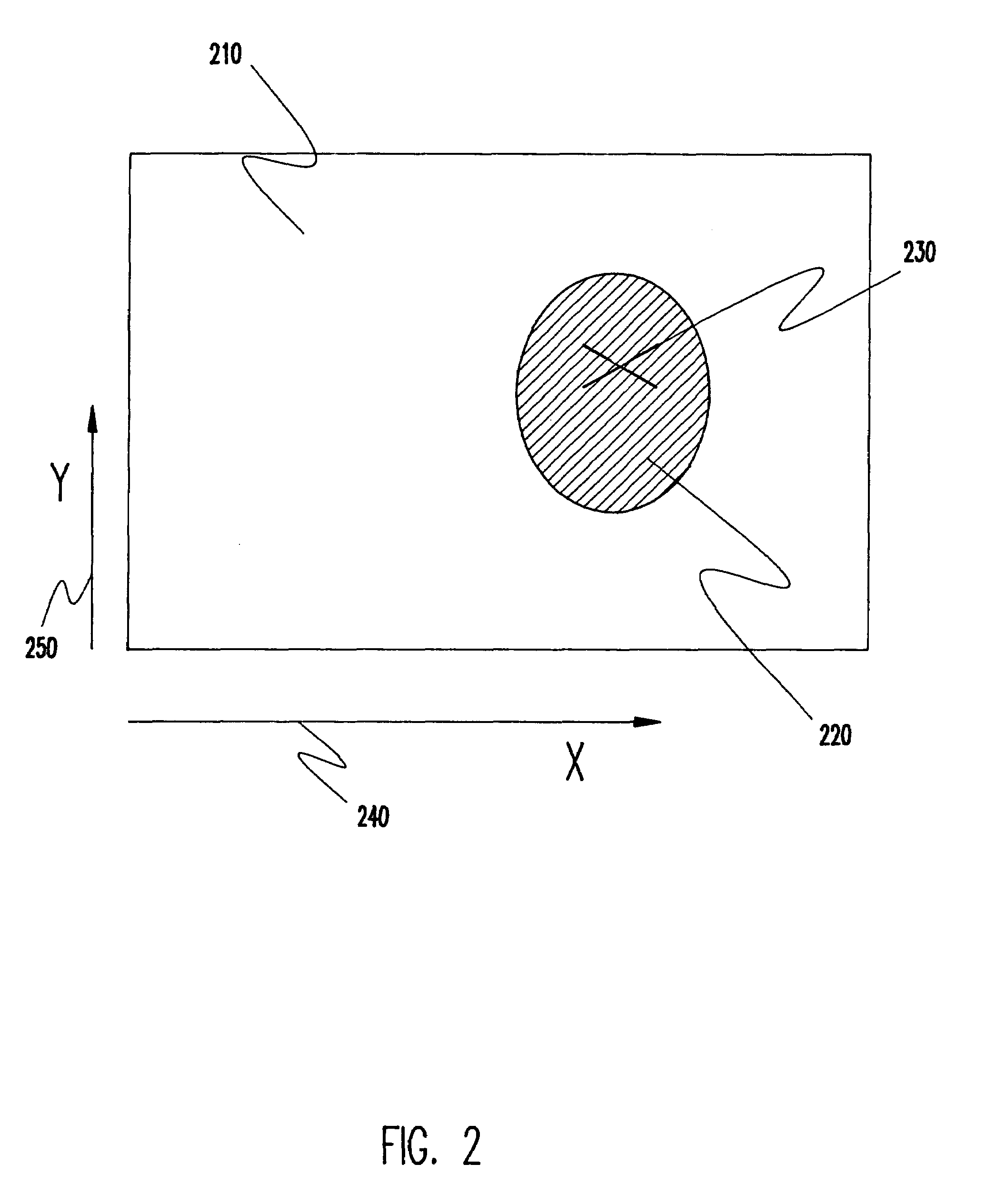
[0027]When comparing two fingerprint images of the same finger acquired from an imaging device (or indeed different capture systems), the patterns in the fingerprints may be different for a number of reasons, including plane rotation: the rotation of the finger about an axis perpendicular to the plane of the scanner. Such a rotation would cause features in the images to rotate about the axis of rotation. Other processes will cause the features to move about in other ways such as translation.

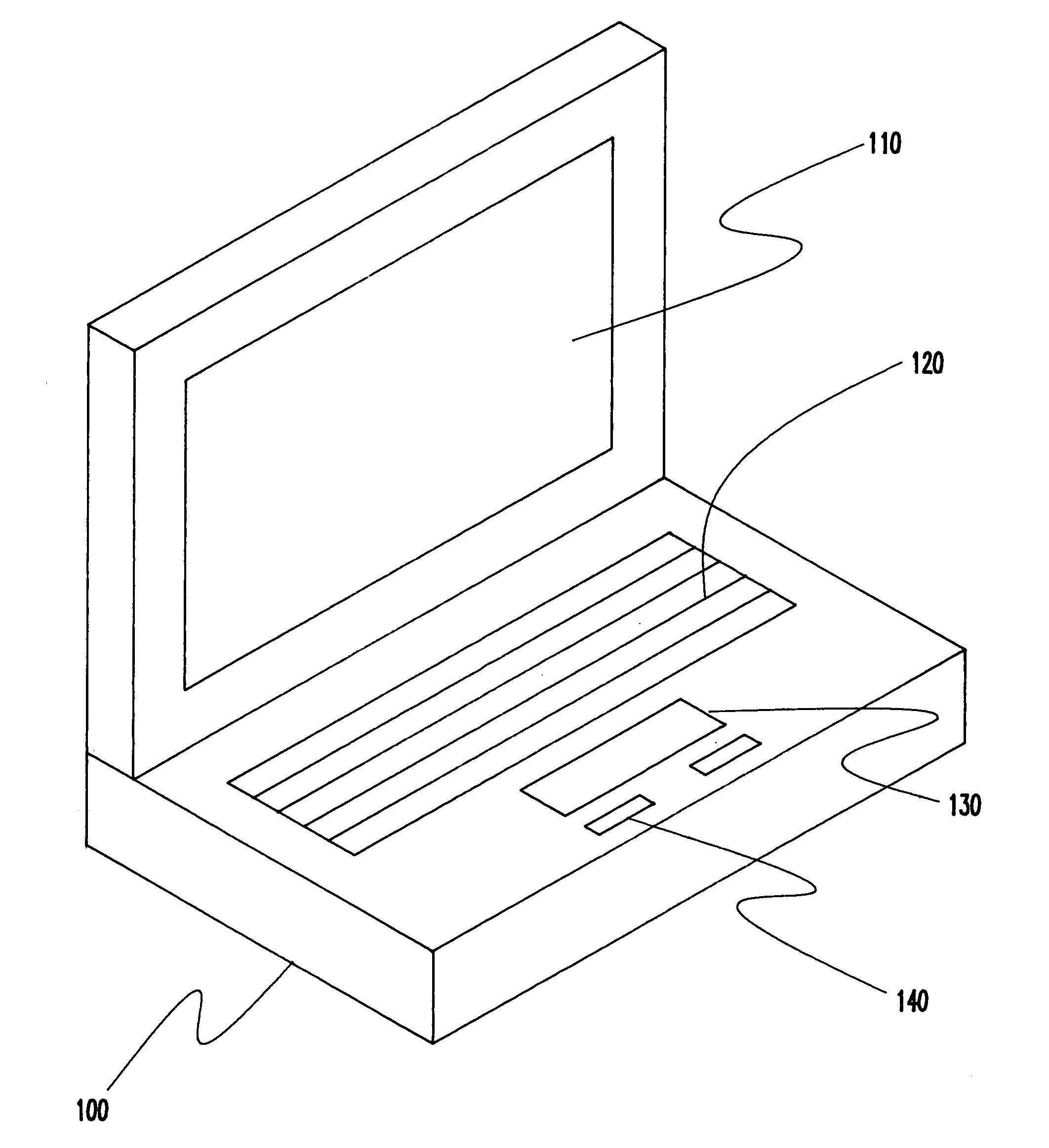
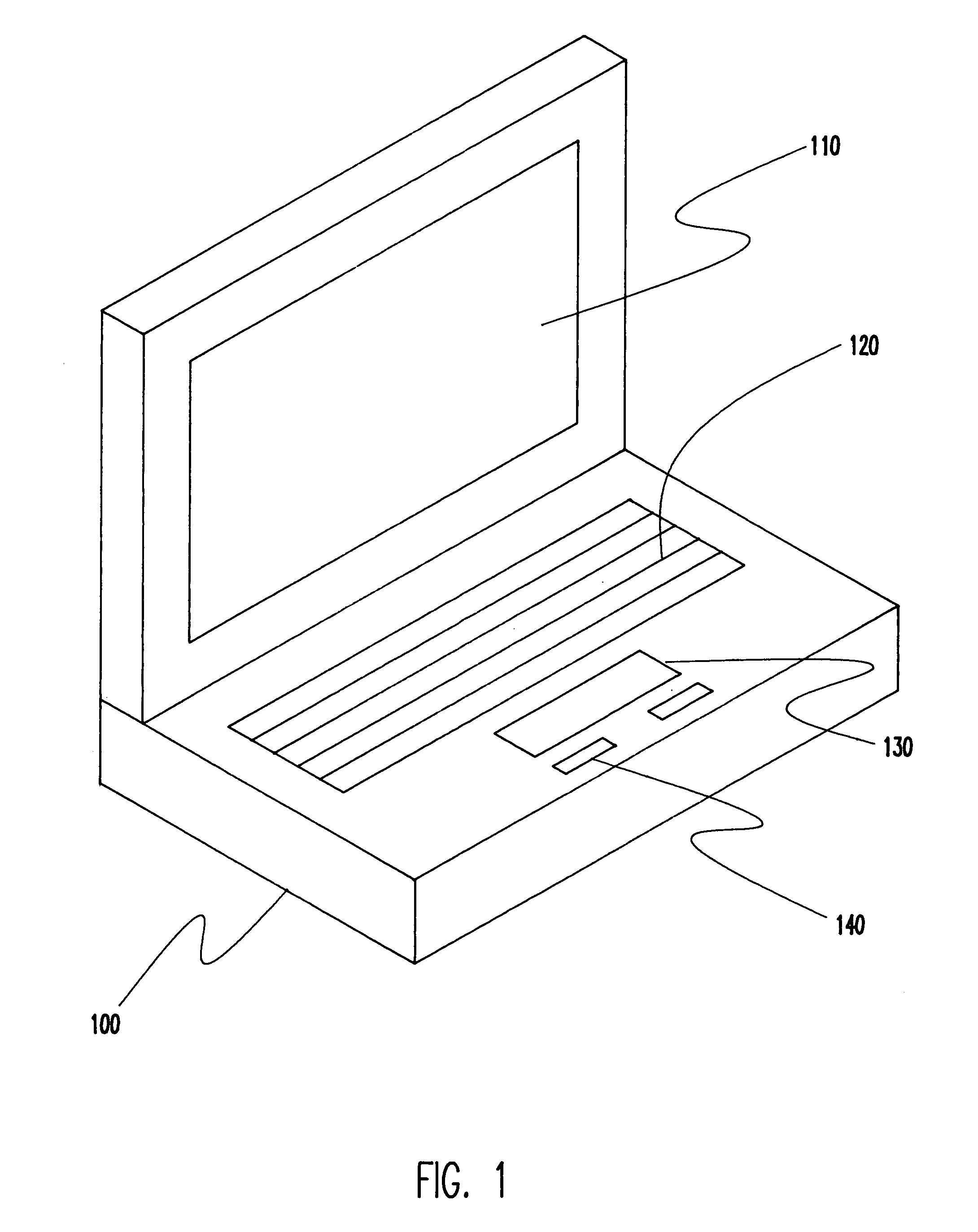
[0028]In operation, the invention may be used as a security device for a mobile computer as shown in FIG. 1. In FIG. 1 there is shown a computer 100, having as screen 110 and keyboard 120. Computer 100 is shown having a combined fingerprint scanner and pointing device scanner 130 according to the present invention. A pair of optional control buttons 140 are also shown. Control buttons 140, may be used, for example, as substitutes for the buttons of a mouse. It should be noted that mobile computer...


PUM


Abstract

The present invention combines the functionality of a computer pointing device with a fingerprint authentication system, In the preferred embodiment, by regularly scanning fingerprints acquired from the pointing device touch pad, fingerprint features may be extracted and compared to stored data on authorized users for passive authentication. Furthermore, calculations based upon the acquired fingerprint images and associated features allows the system to determine six degrees of freedom of the finger, allowing the user to control a variety of functions or to manipulate a three-dimensional model or virtual reality system.

Description

CROSS REFERENCE TO RELATED APPLICATION[0001]This application is a continuation-in-part of U.S. application Ser. No. 09 / 080,322 to Andrew Senior, filed on May 15, 1998, for “Combined Fingerprint Acquisition and Control Device” and assigned to a common assignee herewith, now U.S. Pat. No. 6,400,836. The disclosure of U.S. Pat. No. 6,400,836 is incorporated herein by reference.BACKGROUND OF THE INVENTION[0002]1. Field of the Invention[0003]The present invention generally relates to the field of computer input devices and, more particularly, to pointing devices, fingerprint acquisition devices, and secure fingerprint acquisition.[0004]2. Background Description[0005]Most common computer operating systems presently incorporate windowing in presenting information to users. Common examples of such software, often referred to as graphical user interfaces (GUIs), include Microsoft Corporation's Windows series and Apple Corporation's Mac OS. In such computer systems, a spatial metaphor is used...

Claims


Application Information

Patent Timeline
Patent Type & Authority Patents(United States)
IPC IPC(8): G06F1/16G06K9/00G06F1/00G06F21/00
CPCG06F1/1616G06F1/1684G06F1/169G06F21/32G06K9/00006G06V40/12
Inventor BOLLE, RUDOLF M.RATHA, NALINI K.SENIOR, ANDREW
Owner SYNAPTICS INC
Learn More