
Wireless communications system

Active Publication Date: 2005-09-06
PANASONIC CORP +1
View PDF11 Cites 67 Cited by
  • Summary
  • Abstract
  • Description
  • Claims
  • Application Information

AI Technical Summary

Benefits of technology

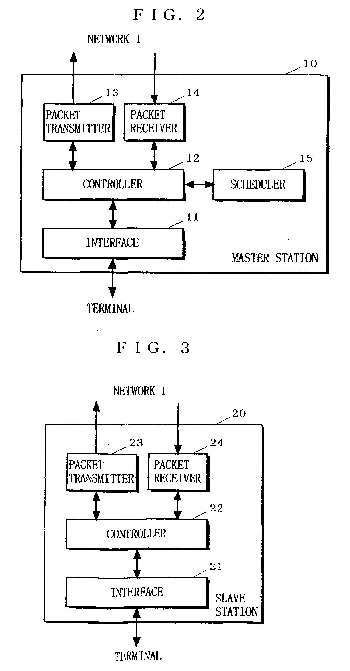
[0042]As such, in the present invention, scheduling results of the scheduler, that is, transmission band assignment results are regularly transmitted to the slave station by using a band assignment packet, and bidirectional data transmission is made by using the assigned transmission band. Thus, for any data of CBR, VBR, ABR, and UBR, a band which is required for data transmission is allocated in advance, and data transmission can be completed by a required end time. Moreover, communication links whose priority is not less than the random number are subjected to scheduling, thereby reducing load on the scheduler.
[0060]Thus, power consumption at the receiving station can be reduced.

Problems solved by technology

However, in conventional wireless communications systems using the CSMA method, if the plurality of PCs each send a transmission request simultaneously, the wireless access devices try to start transmission, leading to transmission collisions on the wireless network.
This is because the wireless access devices can only check whether transmission is actually being made at the time of measuring field intensity.
In other words, the wireless access devices cannot detect transmission that will be made in future.
Moreover, the wireless access devices are not capable of detecting collision, and therefore, the wireless access devices may erroneously determine that transmission has succeeded even though transmission has not succeeded due to collision.
Such collision will occur more frequently as the number of wireless access devices or the number of transmissions that are tried by the wireless access devices increases.
However, such digital video data is generally large in volume, and requires high speed for transmission.
In the above-described conventional wireless communications system using the CSMA method, however, transmission efficiency is low because transmission collisions on the wireless network should be avoided.
Therefore, it is difficult to achieve real-time, high-capacity, high-speed transmission of digital video data.
Therefore, in the conventional wireless communications system, real-time data transmission may be impaired.

Method used


Image

  • Wireless communications system
  • Wireless communications system
  • Wireless communications system

Examples


Embodiment Construction

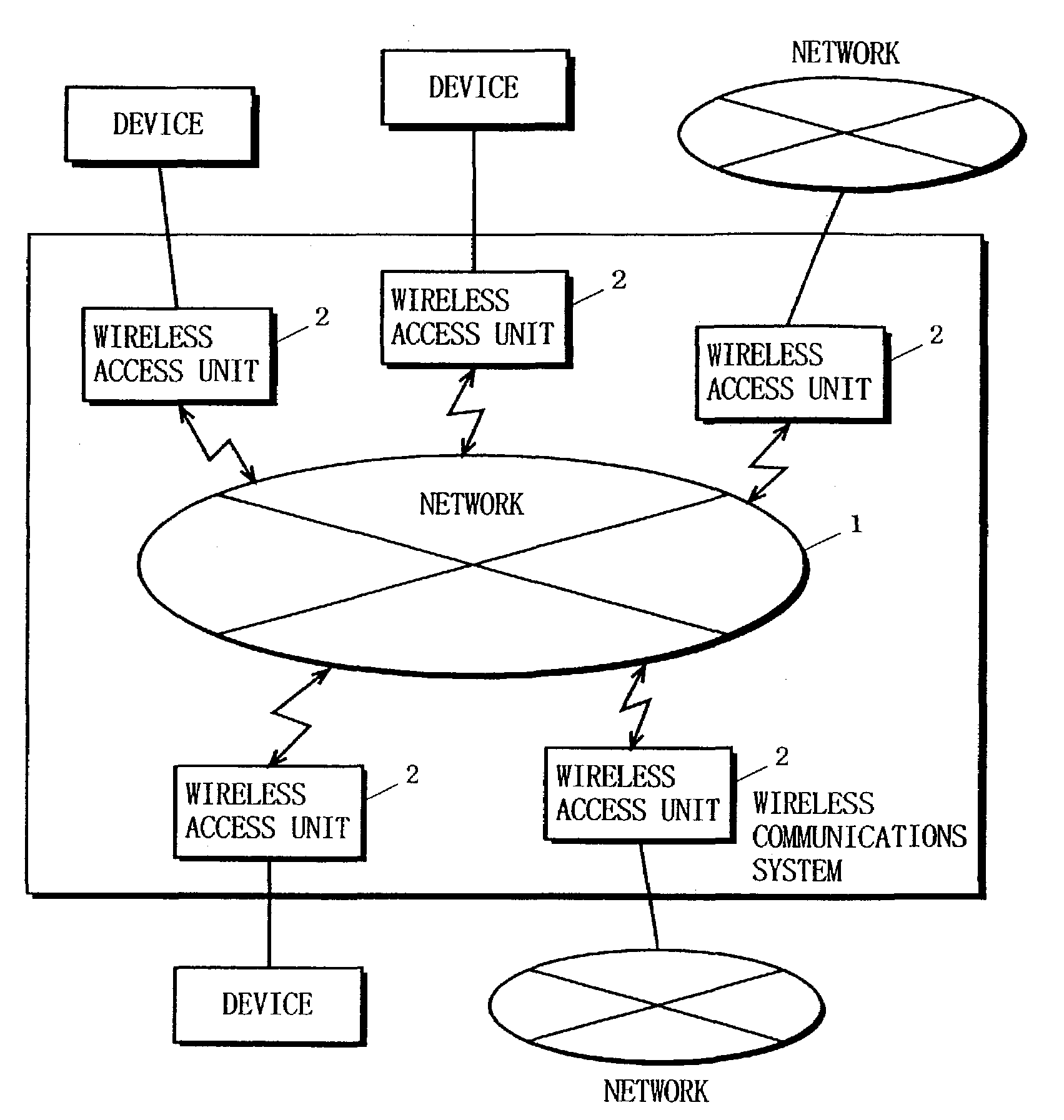
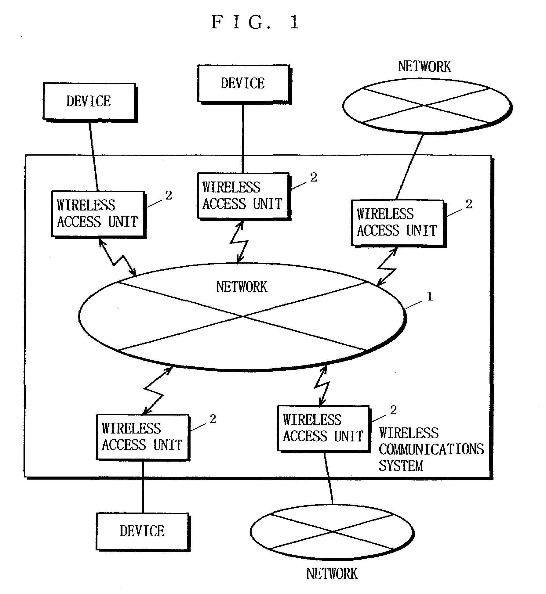
[0081]FIG. 1 is a diagram showing one example of an environment where a wireless communications system according to one embodiment of the present invention is used. As shown in FIG. 1, in the wireless communications system according to the embodiment of the present invention, data transmission is made among devices such as PCs and television receivers and networks (hereinafter collectively referred to as terminals). Such data transmission includes transmission of video images and video signals to a television and access to the Internet. In the wireless communications system, optimal data transmission is achieved by effectively using limited communications resources. In the wireless communications system according to the present embodiment, a plurality of wireless access units 2 that are connected to the respective terminals are provided, and the plurality of wireless access units 2 are wirelessly connected to one another to form a network 1.

[0082]In the present invention, any one of...


PUM


Abstract

A wireless communications system in which real-time data and burst data can be mixedly transmitted, and a transmission band can be dynamically assigned according to a state of data transmission. A master station has a scheduler for determining a transmission band assignment including information about the transmission timing of the data, a transmission amount, and a station that is allowed to access. The scheduler regularly carries out scheduling, and optimizes the transmission band to be assigned dynamically according to the communication type of the data and a state of data transmission. The master station gives a transmission band assignment which is determined by the scheduler to each slave station. A transmitting station executes data transmission (access) to a receiving station based on the given transmission band assignment. The receiving station gives information about a state of data receiving to the master station, where the scheduler reflects this on scheduling.

Description

BACKGROUND OF THE INVENTION[0001]1. Field of the Invention[0002]The present invention relates to wireless communications systems and, more specifically, to a system for data communications among a plurality of terminals which are connected to one another through a wireless network, and a method used therein for scheduling (method for assigning a transmission band for data transmission for each communications link), dividing a data packet, and carrying out re-transmission when an error occurs.[0003]2. Description of the Background Art[0004]There have been various systems for data communications among personal computers (hereinafter, PCs) or between PCs and a host computer connected to one another through a network. A wired network such as Ethernet of IEEE 802.3 and Token-Ring of IEEE 802.5 have been part of the mainstream of such a network. With the advent of portable PC terminals which do not require any wiring, however, such a wired network is gradually shifting to a wireless netwo...

Claims


Application Information

Patent Timeline
IPC IPC(8): H04L12/56H04B7/26H04L1/00H04L7/00H04L12/28H04L47/43H04L47/762H04L47/80H04W28/06H04W72/10H04W72/12H04W88/08
CPCH04W72/1236H04W56/00H04W28/24H04W72/543
Inventor OMI, SHINICHIROHAYASHINO, HIROSHIIMAI, HIROYUKIANDO, KAZUHIRO
Owner PANASONIC CORP
Learn More