Cable loop device for optical systems

Active Publication Date: 2010-12-30
PRYSMIAN CABLES & SYST
View PDF15 Cites 27 Cited by
  • Summary
  • Abstract
  • Description
  • Claims
  • Application Information

AI Technical Summary

Benefits of technology

[0022]The present invention avoids, or at least remarkably reduces, the requirements of storage and congestion of separate splice trays and storage bays known in the art. Therefore, according to the present invention, the optical cables are stored and supported by the periphery of the cable loop device, this resulting in the efficient use of space (that is generally wasted in providing separate units) and in the guiding and distribution of optical fibres within the cables directly to within the cable looping device's fibre storage and work areas. An additional advantage of the present invention is that, as opposed to the known prior art, the cable loop device can be manufactured in one piece, i.e. it can be extruded or moulded as a single unit, thus simplifying the manufacture and providing a saving in material and manufacturing costs.
[0023]As mentioned above, according to the present invention the reduction in storage and congestion of the optical cable within an optical hardware system, such as an optical joint, is achieved by the unique positioning of the cable storage area in relation to the fibre storage and work areas on the cable loop device. This results in efficient use of available storage space and distribution of optical fibre to the fibre storage and work areas. Namely, the present invention allows that the optical cables can be stored, supported by the cable storage area and secured within the cable storage area, whereby optical fibre within the optical cable can be broken out and directly distributed to the fibre storage and work areas using the above mentioned guide tracks without leaving, or being re-routed or distributed from, the cable loop device. This gives the advantage of protecting the optical fibre from damages due to possible bending beyond its minimum bend radius, when the optical fibres are guided to the fibre storage and work areas.
[0024]Preferably, the cable loop storage device further includes a plurality of guide tracks, where a first portion of the guide tracks connects at least one of the fibre storage areas to at least one of the work areas. Preferably, a second portion of the guide tracks connects the cable storage area to at least one of the first portion of the guide tracks. The guide tracks support and protect optical fibre that is guided from the fibre storage areas or cable storage areas to the work areas or elsewhere. The guide tracks are designed to support the optical fibre to prevent the optical fibre from being bent beyond their minimum bend radius.
[0025]Instead of being stored at the entrance or stored and routed through an optical hardware system to a storage area separate from the cable loop device, the cable loop device according to an aspect of the present invention is arranged such that the optical cables are distributed and stored in a continuous loop on the cable loop device from their point of entry / exit into / from the optical hardware system.
[0026]According to an aspect of the present invention, one or more optical cables are routed through at least one common cable port and looped in the cable storage area that is arranged on the periphery of the cable loop device. This aspect improves the management of the optical cables, e.g. within an optical joint, since, during installation, the optical cables are looped and supported on and by the periphery of the cable loop device, where at least one optical fibre is broken out from the optical cable within the cable storage area and routed (i.e. laid onto / into the guide tracks) onto the fibre storage areas or work areas that are preferably centrally located on the cable loop device.
[0027]Preferably, at least one of the cable storage areas is disposed around the periphery of the cable loop device. Preferably, the cable storage area includes an inner periphery that encloses the work and fibre storage areas. This provides for improved storage of optical cable on the cable loop device and allows the optical cable to be looped and supported, by the inner periphery, during installation, storage and maintenance.

Problems solved by technology

This generally causes congestion of the optical joints due to intertwining of the optical cables and / or of the optical fibres during storage and installation.
As more optical cables and fibres are connected to an optical communication system, optical cable and fibre storage, e.g. within the optical joints, becomes evermore difficult.
However, although this may organise the cable / fibres, it also adds to the total congestion within the optical joint and can be considered as being wasteful of the available optical cable / fibre resources in terms of space and used / unused fibre.
As more cables are installed, there is an increased likelihood of optical cable and fibre damage as bending the optical cable and fibres around each other risks bending them beyond their minimum bend radius.
The broken out fibres may be protected with flexible transport tubes, however, the tubes are still required to be stored for excessively lengthy runs of fibre.
However, the remaining optical fibre and cable remain unused and simply take up valuable space within the optical joint.
In fact, since the cables are stored within a central cable looping device, the cables cannot contain more than one optical fibre as any more fibres would not allow the cables to be bent around the central spool.
Moreover, since the cables are stored within a cable looping device which is placed centrally with respect to the splice tray, the cable storage is not efficiently performed principally for the reason that a large area of the splice tray is unused.
Furthermore, the splice tray according to U.S. Pat. No. 6,427,045 does not provide for a storage area for the optical fibres to be worked, e.g. to be spliced.
This results in an inefficient and unsatisfactory use of available space within the optical joint.
This solution provides an inefficient use of storage and also hampers access to the splicing bays as bundles of fibres will need to be removed and untangled.
This inevitably increases the risk of accidental bending of the fibres beyond their minimum bend radii.
The use of clamps and cable ties can cause fatigue of the optical cable material at specific points along the cable.
Similarly, the fragile optical fibres at these points can be damaged.
Further damage can be caused during installation and maintenance as the clamps or ties are tightened / loosened / removed or the hinged covers are removed and replaced when installing / accessing / re-routing the optical cables and bundles of fibres.
In addition, the clamps or ties do not fully support the optical cables or fibres, which are only supported at specific points around the storage bays or splicing trays.
This means that spaced lengths of cable and fibre are completely unsupported, said unsupported lengths being possibly bent in towards the centre of the storage bays or splicing tray and stresses being possibly exerted on these unsupported lengths while they are installed, maintained, and held within the storage bay.
Therefore, this aspect can further contribute to damage and breakage of the cables / fibres.

Method used


Image

  • Cable loop device for optical systems
  • Cable loop device for optical systems
  • Cable loop device for optical systems

Examples


Embodiment Construction

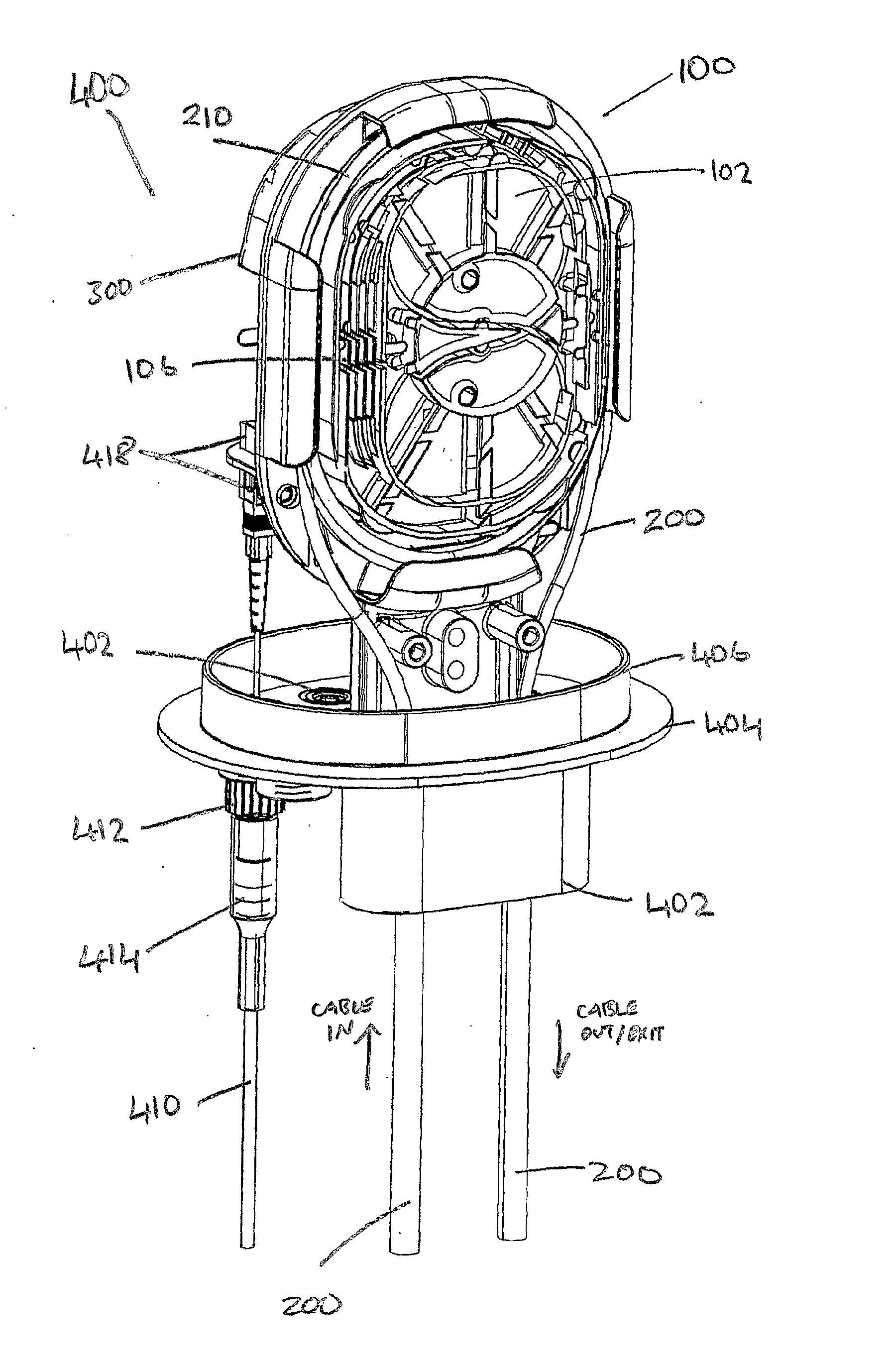
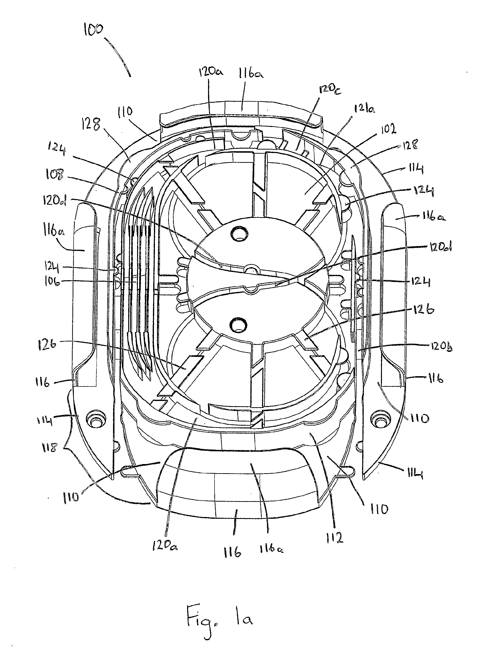
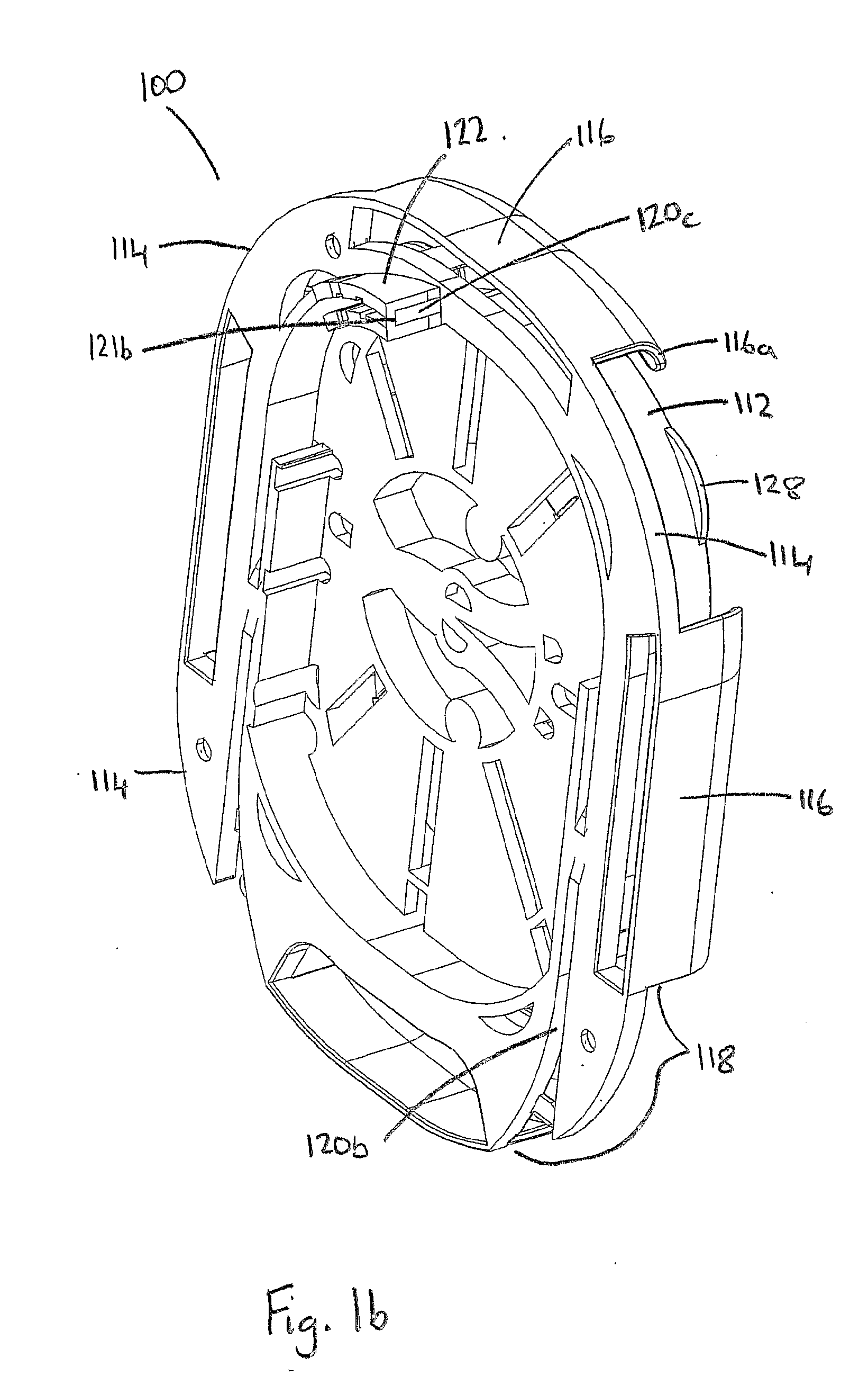
[0073]Two perspective views of a cable loop device 100 for storing, routing and distributing optical cable and optical fibres in an optical system is shown in FIGS. 1a and 1b. Plan and left side elevations of the cable loop device 100 are shown in FIGS. 1c and 1d.

[0074]Referring to FIGS. 1a to 1d, a brief overview of the cable loop device 100 is now given followed by a detailed description of its components and use. The cable loop device 100 includes a fibre storage area 102, a mandrel 104 centrally located within the fibre storage area 102 and a work area 106.

[0075]According to the embodiment shown in the figures, the work area 106 includes four splicing bays. However, the work areas 106 could include other types of bays for working an optical fibre such as by coupling, splitting, terminating or the like. The fibre storage area 102 and work area 106 are enclosed by the periphery 108 of the cable loop device 100. The cable storage areas 110 are disposed on the periphery 108 of the ...


PUM


Abstract

A cable loop device (100) is provided for use in optical systems for storing, routing and distributing optical cables and fibre within optical networks, optical hardware and optical joints thereof. The cable loop device (100) includes one or more work areas (106), one or more fibre storage areas (102), a plurality of guide tracks (120a-120c), and at least one cable storage area (11O), where the at least one cable storage area (110) is disposed on the periphery of the cable loop device (100) for looping optical cable and the fibre guide tracks (120a, 120b) connect the cable storage (110), fibre storage (102) and work (106) areas together. A routing device (300) is provided for use with the cable loop device (100) for routing optical fibre from the routing device (100) through to a third portion of guide tracks (120c) disposed through the cable loop device (100) for splicing to fibres therein. A method for looping optical cable and routing a portion of optical fibre therein is provided for use with the cable loop device (100).

Description

FIELD OF THE INVENTION[0001]The present invention relates to a cable loop device for use in optical systems. In particular, the present invention relates to the storage, management and distribution of optical cables and optical fibres within optical networks, optical hardware or optical joints thereof.BACKGROUND[0002]Optical communication systems require the laying down of numerous optical cables and fibres. These are connected together using various forms of optical fibre hardware such as optical joints, e.g. optical fibre closures or splicing enclosures. Optical joints are used for storing and managing optical cable and fibre connections and providing work areas in which optical cables and fibres can be worked, for example coupled, split, spliced, terminated or the like. Hereinafter, the operations which are carried out on the optical cables and / or optical fibres—such as coupling, splitting, splicing, terminating—are referred, to as working the cables / fibres. In the optical joint,...

Claims


Application Information

Patent Timeline
IPC IPC(8): G02B6/00G02B6/46
CPCG02B6/4442
Inventor GRIFFITHS, IANHUBBARD, PAUL
Owner PRYSMIAN CABLES & SYST
Why Eureka
Try Eureka