
Static pressure calculation from dynamic pressure for rotary air-data system and methodology therefor

a dynamic pressure and calculation technology, applied in the field of airspeed measurement systems for rotary wing aircraft, can solve problems such as significant accuracy degradation, and achieve the effect of improving the ability of rotary aircra

Active Publication Date: 2005-09-06
SIKORSKY AIRCRAFT CORP
View PDF10 Cites 8 Cited by
  • Summary
  • Abstract
  • Description
  • Claims
  • Application Information

AI Technical Summary

Benefits of technology

[0008]Mathematical techniques are employed which provide accurate airspeed computations without a static pressure sensor along with inherent noise immunity such as the turbulent flow generated when the main rotor blade passes over the fuselage or tail wake.
[0010]The RADS also computes the direction of the relative wind. This is particularly useful when the pilot executes hover or low speed, low altitude maneuvers in restricted visibility. The availability of relative wind velocity information coupled with navigation data enhances the ability of rotary aircraft to perform accurate low altitude hover, fire control and other autopilot maneuvers.
[0011]The present invention therefore provides an uncomplicated air-data system for a rotary wing aircraft which avoids the utilization of static pressure sensors while assuring accurate data over a broad range of airspeeds and directions.

Problems solved by technology

The RADS performs the combined functions of a conventional air-data system, which historically experience significant accuracy degradation at low air speeds due to main rotor down wash and a low airspeed sensing system in integrated seamless manner.

Method used


Image

  • Static pressure calculation from dynamic pressure for rotary air-data system and methodology therefor
  • Static pressure calculation from dynamic pressure for rotary air-data system and methodology therefor
  • Static pressure calculation from dynamic pressure for rotary air-data system and methodology therefor

Examples


Embodiment Construction

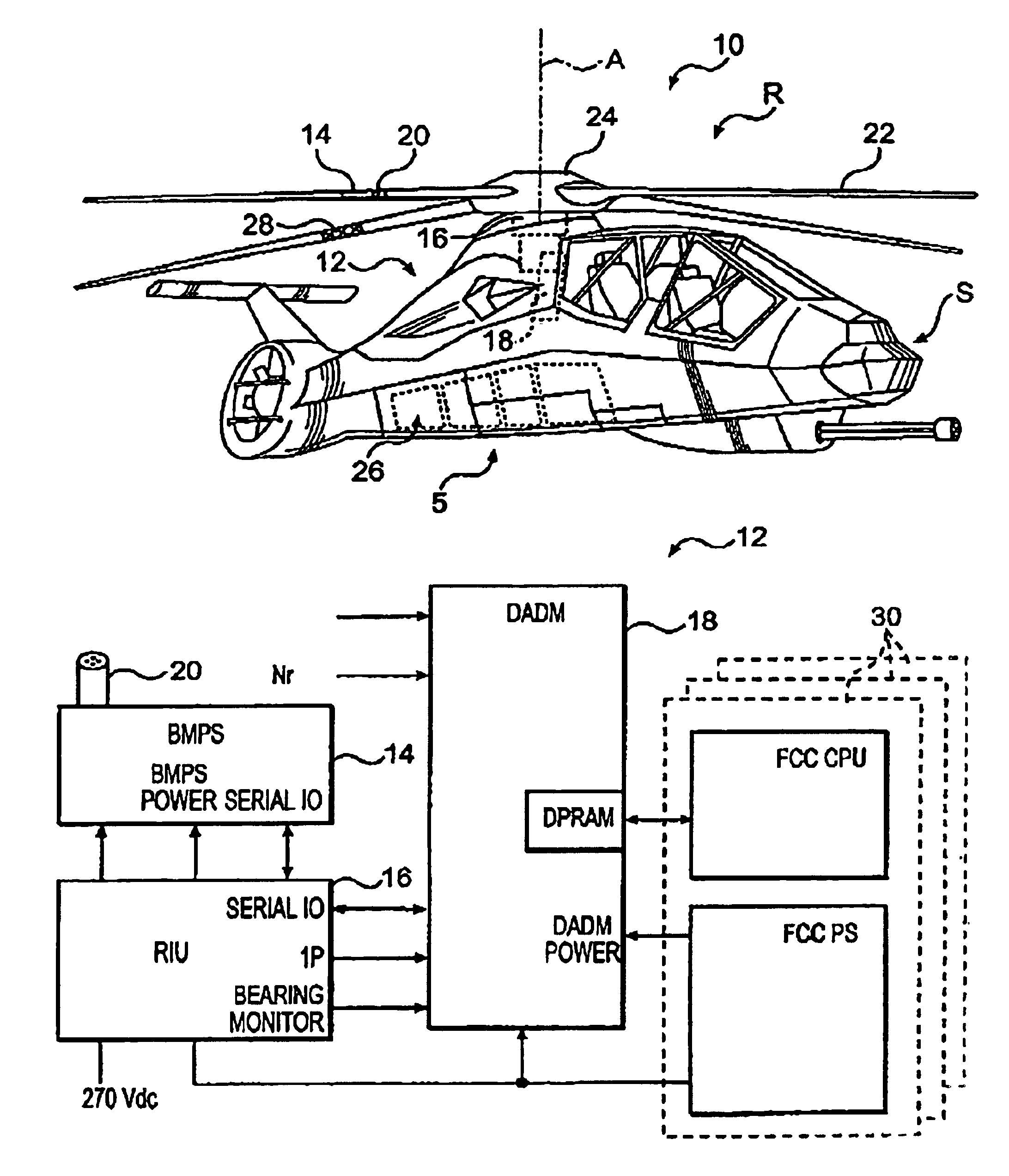
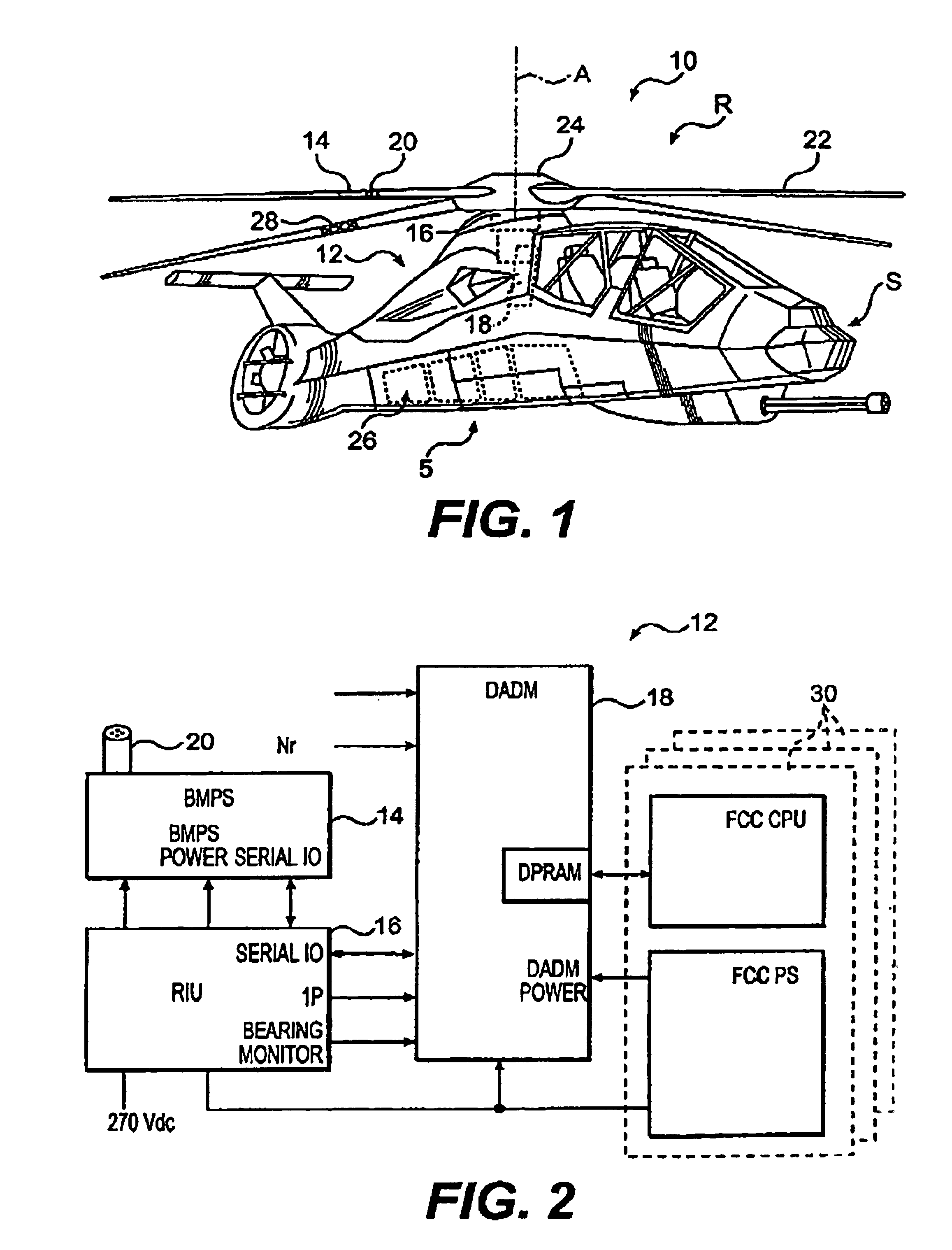
[0019]FIG. 1 schematically illustrates a vehicle 10 such as a RAH-66 Comanche helicopter, which includes a rotary air data system (RADS illustrated generally at 12). It should be understood that although a particular vehicle is disclosed in the illustrated embodiment, other vehicles would benefit from the instant invention.

[0020]The complete RADS 12 as installed on an aircraft preferably includes three separate channels that independently provide airspeed information to each of the three Flight Control Computers (FCCs) 30 (FIG. 2). Availability of three independent channels of air-data provides the potential to perform redundancy management.

[0021]The RADS 12 includes a Blade mounted Pressure Sensor (BMPS) 14 having a Pitot Scoop 20, a Rotary Interface Unit (RIU) 16, and a Digital Air Data Module (DADM) 18. A rotational field R includes a multiple of rotor blades 22 and rotor hub assembly 24 which rotate about an Axis A relative to a stationary field S defined by the vehicle airframe...


PUM


Abstract

A Rotary Air-data System (RADS) periodically samples pressure data from a main rotor blade mounted pitot-scoop integrated with a high accuracy pressure sensor to compute a velocity vector that is resolvable into the aircraft's coordinate system. Mathematical techniques are employed which provide accurate computations of static pressure without a static pressure sensor. The RADS also computes the direction of the relative wind which is particularly useful when the pilot executes hover or low speed, low altitude maneuvers in restricted visibility. The availability of relative wind velocity information coupled with navigation data enhances the ability of rotary aircraft to perform accurate low altitude hover, fire control and other autopilot maneuvers.

Description

BACKGROUND OF THE INVENTION[0001]The present invention relates to aircraft instrumentation, and more particularly to airspeed measurement systems for rotary wing aircraft.[0002]Aircraft air-data information is required for aerodynamic control. Typically, aircraft speed is measured by pitot-static systems that provide indicated airspeed, that is, the ram or dynamic pressure compared to the static pressure for the particular altitude. The indicated airspeed provides information to the pilot for aerodynamic speed control.[0003]Indicated airspeeds are dependent on air density and may be significantly different from true airspeed. Conventional systems generally measure indicated airspeed and use an air data computer or other calculating means to determine true speed. Several problems arise with existing devices as measurement accuracy is dependent on the alignment of the pitot head with the incoming airflow. At large yaw angles or at high angles of attack, significant errors may also be ...

Claims


Application Information

Patent Timeline
Patent Type & Authority Patents(United States)
IPC IPC(8): G01C21/00G01P5/16G01P13/02
CPCG01P5/16G01P13/02G01P13/025
Inventor KAUSHIK, RAJINDAR P.HAESCHE, JAMES A.VERSAILLES, RICHARD E.
Owner SIKORSKY AIRCRAFT CORP
Learn More